Self-Generation
Incentive Program
Self-Generation
Incentive Program
HANDBOOK
Provides financial incentives for installing
clean, efficient, on-site distributed
generation
August 1, 2023
V.3

1
What’s New Self-Generation Incentive Program (SGIP)
The 2023 V3 Handbook has been updated to reflect the following changes:
• Structural Modifications
o Revised layout of Handbook for easier navigation
o Deleted redundant and outdated footnotes and Regulatory Background
o Updated web links and improved accessibility of hyperlinks
• Language Changes
o Adjusted language for consistency
o Language correction for Capacity Equations (§ 6.4.1, § 6.4.2)
o Revised date for Legacy Residential Projects (§ 6.2.5)
• Proposed Language Additions
o Clarification regarding Budget Allocations (§ 1.1)
o Clarification of the Lottery Procedure in Final Budget Step (§ 2.1.1.1.3)
o New footnote about Heat-Pump Water Heater Program (§ 1.2)
o Clarification on Data Requirements Thermal Energy Storage Systems (§ 2.1.1.3,
Appendix G)
o Clarification on renter eligibility (§3.1)
o Clarification of Developer eligibility (§3.6)
o Two additional participant chapters (§3.7, §3.8)
o Additional language on Resiliency Adder (§4.1.1)
o New sub-chapter on the Generation Budget (§4.1.3)
o Additional language on SGIP eligible equipment (§5)
o Clarification on interconnection requirements (§5)
o Additional language on system sizing without peak demand information (§ 6.3)
o Additional language on Rated and Energy Capacity Calculations for HVAC-integrated S-
TES Systems (§ 6.4.1, § 6.4.2, § 8.1, Appendix H)
o Additional language on Proof of Critical Facility (§8.1)
o Clarification on Authority Having Jurisdiction (AHJ) Stamp Requirements on AHJ
Approved Grid Island Capable Plans (AAGICP) (§ 8.3)
• Additions and Clarifications in the Glossary
o Added Large Thermal Energy Storage (L-TES)
o Clarification on existing terms

2
Contents
What’s New Self-Generation Incentive Program (SGIP) .............................................................................. 1
Program Administrator Contact Information .................................................................................................. 8
Program Overview ........................................................................................................................................ 9
1 Budget .................................................................................................................................................. 10
1.1 Statewide Program Budget and Administrator Allocations ......................................................... 10
1.2 Budget Allocation ........................................................................................................................ 10
2 Applications .......................................................................................................................................... 11
2.1 Application Process ..................................................................................................................... 11
2.1.1 Application Process Flowchart ................................................................................................ 11
2.1.1.1 Application Submissions ................................................................................................. 12
2.1.1.1.1 Residential Storage “Soft Target” ............................................................................. 13
2.1.1.1.2 Developer Caps ........................................................................................................ 13
2.1.1.1.3 Lottery Process ......................................................................................................... 13
2.1.1.1.4 Pause Periods ........................................................................................................... 14
2.1.1.1.5 Waitlists ..................................................................................................................... 15
2.1.1.2 Incomplete Applications .................................................................................................. 15
2.1.1.3 Post-Installation Inspections ........................................................................................... 15
2.1.2 Application/Project Modifications, Extensions and Cancellations ........................................... 16
3 Program Participant Eligibility .............................................................................................................. 20
3.1 Host Customer ............................................................................................................................ 20
3.2 Host Customer Eligibility for the Equity, Equity Resiliency, and San Joaquin Valley Budgets ... 20
3.2.1 Residential Equity Eligibility .................................................................................................... 20
3.2.2 Non-Residential Equity Eligibility ............................................................................................. 23
3.2.3 Residential Equity Resiliency Eligibility ................................................................................... 24
3.2.4 Non-Residential Equity Resiliency Eligibility ........................................................................... 25

3
3.2.5 San Joaquin Valley Eligibility .................................................................................................. 28
3.3 Classification of Multifamily Properties ....................................................................................... 28
3.4 System Owner ............................................................................................................................. 29
3.5 Applicant ...................................................................................................................................... 30
3.6 Developer .................................................................................................................................... 30
3.7 Installer ........................................................................................................................................ 32
3.8 Performance Data Provider ......................................................................................................... 32
3.9 Payee .......................................................................................................................................... 32
3.10 Entity ........................................................................................................................................... 33
4 Incentives ............................................................................................................................................. 34
4.1 Incentive Rates............................................................................................................................ 34
4.1.1 General Market Energy Storage Budgets ............................................................................... 34
4.1.2 Energy Storage Equity and Pilot Budgets ............................................................................... 35
4.1.3 Renewable Generation Budget ............................................................................................... 37
4.1.3.1 Renewable Generation Resiliency Adder ....................................................................... 35
4.2 Incentive Calculation ................................................................................................................... 35
4.2.1 Energy Storage Technologies ................................................................................................. 35
4.2.1.1 Incentive Declines Based on Storage Duration .............................................................. 36
4.2.1.2 Incentive Declines and Caps Based on Energy Capacity (Wh) ...................................... 36
4.2.2 Renewable Generation Technologies ..................................................................................... 37
4.2.3 Incentive Declines Based on Generation Rated Capacity ...................................................... 37
4.3 Performance-Based Incentive (PBI) Payment ............................................................................ 37
4.3.1 Energy Storage Technologies ................................................................................................. 37
4.3.1.1 Performance-Based Incentive (PBI) GHG Performance Penalty ................................... 38
4.3.2 Renewable Generation Technologies ..................................................................................... 38
4.3.2.1 PBI Payment Exceedance Cap for Generation Projects................................................. 39
4.3.2.2 PBI Payments for Export to the Grid Projects ................................................................. 39

4
4.4 California Manufacturer Adder .................................................................................................... 39
4.4.1 Eligibility Criteria and Verification ............................................................................................ 39
4.4.2 Project Equipment Verification ................................................................................................ 40
4.4.3 How to Determine Value ......................................................................................................... 40
4.5 Incentive Limitations .................................................................................................................... 40
4.5.1 Maximum Incentive Amount .................................................................................................... 41
4.5.2 Total Eligible Project Costs ..................................................................................................... 41
4.5.3 Incentive Calculation for Site with Multiple Systems ............................................................... 42
4.5.4 Calculating Incentives with Existing Systems ......................................................................... 42
4.5.5 Calculating Incentives for System Replacements ................................................................... 43
4.5.6 Incentives from Other Sources ................................................................................................ 43
5 Program Equipment Requirements ..................................................................................................... 45
6 Energy Storage Technologies ............................................................................................................. 48
6.1 Eligibility Requirements ............................................................................................................... 48
6.1.1 Operational Requirements ...................................................................................................... 48
6.1.2 Paired with On-site Renewables ............................................................................................. 48
6.1.3 Demand Response Dual Participation .................................................................................... 48
6.2 Greenhouse Gas (GHG) Requirements ...................................................................................... 49
6.2.1 Greenhouse Gas Signal .......................................................................................................... 49
6.2.2 New Non-Residential Projects ................................................................................................ 50
6.2.3 Legacy Non-Residential Projects ............................................................................................ 50
6.2.4 New Residential Projects ........................................................................................................ 51
6.2.5 Legacy Residential Projects .................................................................................................... 51
6.3 System Size Parameters ............................................................................................................. 52
6.4 Rating Criteria ............................................................................................................................. 53
6.4.1 Rated Capacity (kW) ............................................................................................................... 53

5
6.4.2 Energy Capacity (kWh) ........................................................................................................... 54
7 Renewable Generation Technologies.................................................................................................. 57
7.1 Operational Eligibility Requirements ........................................................................................... 57
7.1.1 Locational Requirements – IC Engines ................................................................................... 58
7.2 Capacity Factors ......................................................................................................................... 58
7.3 Sizing Requirements ................................................................................................................... 59
7.3.1 System Sizing Limitations - Ineligible Host Customer Loads .................................................. 60
7.4 Renewable Fuel Eligibility Requirements .................................................................................... 61
7.4.1 Directed Biogas Projects ......................................................................................................... 61
7.4.1.1 Directed Biogas Project Renewable Fuel and Fuel Source Audits ................................. 61
7.4.2 On-site Biogas Project Gas Quality Standard for IC Engines ................................................. 62
7.4.3 Hydrogen Projects ................................................................................................................... 62
7.4.4 Pressure Reduction Turbines .................................................................................................. 63
7.5 Fuel Documentation Requirements for PBI ................................................................................ 63
8 Documentation Requirements ............................................................................................................. 65
8.1 Reservation Requests ................................................................................................................. 65
8.2 Proof of Project Milestone ........................................................................................................... 81
8.3 Incentive Claim ............................................................................................................................ 84
9 Metering & Monitoring Requirements .................................................................................................. 88
9.1 Electrical Metering Requirements ............................................................................................... 88
9.1.1 Minimum Electrical Metering Requirements for Energy Storage & Generation Projects ........ 89
9.1.2 Small Thermal Energy Storage Technologies ........................................................................ 91
9.1.3 Refrigeration Thermal Energy Storage Technologies ............................................................. 91
9.1.4 Large Thermal Energy Storage Technologies ........................................................................ 91
9.2 Thermal & Fuel Metering Requirements ..................................................................................... 92
10 Performance Data Provider (PDP) ...................................................................................................... 95
10.1 Application Process ..................................................................................................................... 95

6
10.2 Data Transfer Test ...................................................................................................................... 95
10.3 Metering Requirements ............................................................................................................... 95
10.4 Data Reporting and Transfer Rules ............................................................................................ 96
10.4.1 Data Format ............................................................................................................................ 97
10.4.2 Meter Reading and Data Submission Timeline ....................................................................... 98
10.4.3 Online Submission Process .................................................................................................... 98
10.4.4 PDP Data Validation ............................................................................................................... 98
10.4.5 Data Audits & Payment Validation .......................................................................................... 99
10.4.6 Performance Exemptions ........................................................................................................ 99
10.4.7 Non-Performance .................................................................................................................... 99
10.4.8 Data Retention ...................................................................................................................... 100
10.4.9 Technical and Customer Support .......................................................................................... 101
10.4.10 Program Administrator Liability ............................................................................................. 101
10.5 Data Privacy and Security ......................................................................................................... 101
11 Measurement & Evaluation (M&E) Activities ..................................................................................... 102
11.1 M&E Field Visits ........................................................................................................................ 102
11.2 M&E Metering Requirements .................................................................................................... 102
11.3 Disposition of SGIP Metering Equipment .................................................................................. 102
12 Dispute Resolution ............................................................................................................................. 104
13 Participant Performance and Infractions............................................................................................ 105
13.1 Participant Performance ............................................................................................................ 105
13.1.1 File Retention ........................................................................................................................ 107
13.2 Infractions .................................................................................................................................. 107
13.2.1 Issuance of Warnings and Infractions ................................................................................... 107
14 Program Modification Guidelines ....................................................................................................... 108
Definitions and Glossary ........................................................................................................................... 110
Appendix A – Combustion Emission Credit Calculation ........................................................................... 118

7
Appendix B – Conversion of Emissions PPM to Lb/MWH ........................................................................ 121
Appendix C – Conversion Tables for HVAC-Integrated S-TES ................................................................ 123
Appendix D – Calculation of Minimum Roundtrip Efficiency ..................................................................... 125
Appendix E – Incentive Rate for Large-Scale Storage Projects Claiming the ITC at All Incentive Levels 126
Appendix F – Lg. Thermal Energy Storage UC Davis Methodology for Determining 1-in-10 Year Peak. 127
Appendix G – Lg. Thermal Energy Storage Upfront and PBI Incentive Calculation Methodology ........... 129
Appendix H – Incentive Calculation Examples ......................................................................................... 135

8
Program Administrator Contact Information
Potential program participants can obtain information and apply for incentive funding through the following
Program Administrators:
1
Pacific Gas & Electric (PG&E)
Website:
www.pge.com/sgip
Email Address:
Telephone:
(415) 973-6436
Mailing Address:
PG&E Payment Research
Attn: Self-Generation Incentive Program
PO Box 997310
Sacramento, CA 95899
Center for Sustainable Energy® (CSE)
Website:
https://sgipsd.org/
Email Address:
Telephone:
(858) 244-1177
Mailing Address:
Center for Sustainable Energy
Attn: Self-Generation Incentive Program
3980 Sherman Street,
Suite 170
San Diego, CA 92110
Southern California Edison (SCE)
Website:
www.sce.com/SGIP
Email Address:
Telephone:
(626) 302-0610
Mailing Address:
Self-Generation Incentive Program
Southern California Edison
P.O. Box 800
Rosemead, CA 91770-0800
Southern California Gas Company (SoCalGas)
Website:
https://www.socalgas.com/for-your-
business/power-generation/self-generation-
incentive
Email Address:
selfgeneration@socalgas.com
Mailing Address:
Self-Generation Incentive Program
Southern California Gas Company
555 West Fifth Street, GT19A9
Los Angeles, CA 90013-1011
1
Potential eligible projects located in the service territory of both Southern California Edison and the Southern California Gas
Company can apply for incentive funding to either Program Administrator, but not to both.

9
Program Overview
The Self-Generation Incentive Program (SGIP) provides financial incentives for the installation of new
qualifying technologies that are installed to meet all, or a portion of the electric energy needs of a facility.
The purpose of the SGIP is to contribute to Greenhouse Gas (GHG) emissions reductions, demand
reductions and reduced customer electricity purchases, resulting in the electric system reliability through
improved transmission and distribution system utilization; as well as market transformation for distributed
energy resource (DER) technologies.
This handbook outlines the policies and procedures of the SGIP for potential program participants and
other interested parties. The SGIP has been approved by the California Public Utilities Commission
(CPUC) and is subject to change in whole or in part at any time without prior notice. Changes to the
program shall be published in revisions to this Handbook. The Program Administrators (PAs) are Pacific
Gas and Electric (PG&E), Southern California Edison (SCE), the Southern California Gas Company
(SoCalGas) and Center for Sustainable Energy
®
(CSE).
2
2
CSE is the Program Administrator for San Diego Gas & Electric (SDG&E) customers.

10
1 Budget
1.1 Statewide Program Budget and Administrator Allocations
Authorized incentive collections during program years 2020 through 2024 total $813,400,000. Authorized
incentive collections for each Program Administrator are as follows:
Pacific Gas and Electric Company $360,000,000
Southern California Edison Company $280,000,000
Center for Sustainable Energy $99,000,000
Southern California Gas Company $74,400,000
The SGIP shall be administered on a continuous basis. Program Administrators will issue incentive
reservations for any budget with available funds through December 31, 2025.
3
Should it appear likely that
funds will remain unspent, the PAs may transfer funds between budgets prior to December 31, 2025. A
budget overview, including funding availability and current incentive rates, can be found at
www.selfgenca.com/home/program_metrics/.
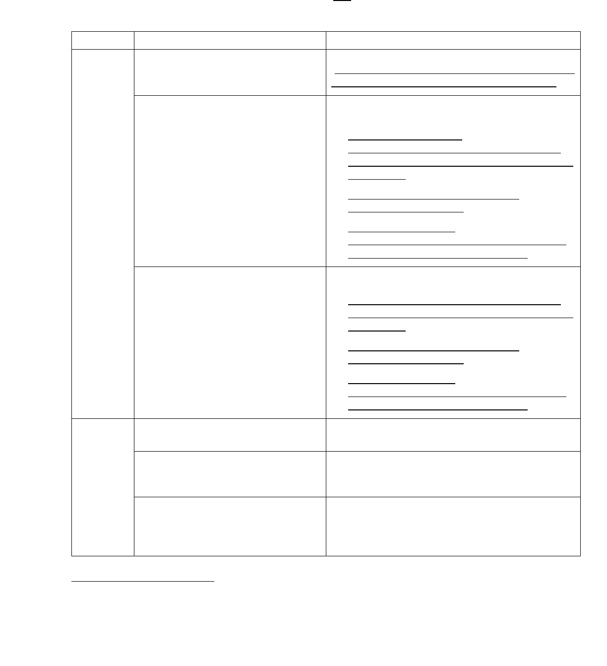
1.2 Budget Allocation
Statewide budget allocations of the 2020 – 2024 ratepayer collections are as follows:
Table 1.2: Statewide budget allocations
Renewable Generation
12%
Energy Storage Technologies
88%
Large-Scale Storage
10%
Small Residential Storage
7%
Residential Equity
3%
Non-Residential Equity
0%
Equity Resiliency
63%
Heat Pump Water Heaters
5%
4
SJV Pilot Budget
0%
3
Incentive funds include authorized ratepayer collections, returned funds from project attrition, application fee forfeitures, and
accrued interest.
4
D.22-04-036, Ordering Paragraph 8, authorized an additional collection of $40M from 2023 Cap-and-Trade Program allowance
auction funds from SoCalGas, PG&E, and SDG&E for the HPWH subprogram.
11
2 Applications
2.1 Application Process
Applications are subject to the incentive rates of the Program Administrator to which they apply.
Generally, applications will be assigned an incentive rate and reviewed in the order in which they are
received. A lottery will be conducted in the event that application submissions for a given budget and step
on a single day exceed the available funding in a given Program Administrator’s territory. Additional
details regarding the lottery process can be found in Section 2.1.1.1.3.
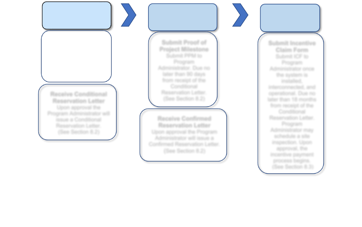
2.1.1 Application Process Flowchart
The application process is determined by the customer sector and system size. There are two application
processes illustrated below:
1. Three-Step Application Process – Figure 2.1.1a
• Non-residential projects 10 kW or greater
2. Two-Step Application Process – Figure 2.1.1b
• All residential projects
• Non-residential projects less than 10 kW
Figure 2.1.1a: Three-Step Application and Approval Process
Reservation
Request (RRF)
Proof of Project
Milestone
(PPM)
Incentive
Claim
(ICF)
Submit Reservation
Request Form
Submit completed RRF
to Program
Administrator.
(See Section 8.1)
Submit Proof of
Project Milestone
Submit PPM to
Program
Administrator. Due no
later than 90 days
from receipt of the
Conditional
Reservation Letter.
(See Section 8.2)
Receive Conditional
Reservation Letter
Upon approval the
Program Administrator will
issue a Conditional
Reservation Letter.
(See Section 8.2)
Receive Confirmed
Reservation Letter
Upon approval the Program
Administrator will issue a
Confirmed Reservation Letter.
(See Section 8.2)
Submit Incentive
Claim Form
Submit ICF to
Program
Administrator once
the system is
installed,
interconnected, and
operational. Due no
later than 18 months
from receipt of the
Conditional
Reservation Letter.
Program
Administrator may
schedule a site
inspection. Upon
approval, the
incentive payment
process begins.
(See Section 8.3)

12
Figure 2.1.1b: Two-Step Application Process
2.1.1.1 Application Submissions
All SGIP applications and required documents
5
are submitted via the SGIP online application database at
www.selfgenca.com. To submit an application and/or project documentation, companies or individuals
must create an Applicant Account and register any anticipated users. All Applicants and Applicant
Administrators must also agree to the SGIP online application database Terms of Use. Terms of Use can
be found at www.selfgenca.com/terms_of_use/. Mailed, emailed, faxed, or hand delivered
applications will not be accepted.
Only complete applications may be assigned incentive funds or be placed into a lottery. Only complete
applications may receive an approved reservation. Duplicate applications or multiple submissions for the
same project are not allowed and will be rejected.
6
5
With the exception of the application fee check that is to be mailed directly to the Program Administrator. See Section 8.1 for more
information.
6
Duplicate applications are considered a program infraction. See Section 13 for information on program infractions. Definition of
project can be found in Definitions and Glossary.
Reservation
Request Form
(RRF)
Incentive
Claim Form
(ICF)
Submit Reservation
Request Form
Submit completed RRF to
Program Administrator.
(See Section 8.1)
Submit Incentive
Claim Form
Submit ICF to
Program
Administrator once
the system is
installed,
interconnected, and
operational. Due no
later than 12 months
from receipt of the
Confirmed
Reservation Letter.
Program
Administrator may
schedule a site
inspection. Upon
approval, the
incentive payment
process begins.
(See Section 7.3)
Receive Conditional
Reservation Letter
Upon approval the
Program Administrator
will issue a Confirmed
Reservation Letter.
(See Section 8.3)

13
2.1.1.1.1 Residential Storage “Soft Target”
The Residential Storage Soft Target reserves 50% of the Step 6 and Step 7 general market small
residential budget for:
• Residential customers living in Tier 3 or Tier 2 High Fire Threat Districts (HFTDs); and/or
• Residential customers whose electricity has been turned off during two or more discrete Public
Safety Power Shutoff (PSPS) events; and/or
• Residential customers who have experienced one PSPS event and one de-energization or power
outage from an actual wildfire that occurred on or after January 1, 2017.
Acceptance of Step 6 and Step 7 general market residential incentive budget applications that do not
meet the criteria outlined above will be paused after such applications reach 50% of the total budget for
each residential incentive step. Acceptance of applications will resume if applications that do not meet the
above criteria drop below 50% of the funding in that budget step.
2.1.1.1.2 Developer Caps
Any single Developer is limited to 20% of the SGIP incentive funding for a given general market budget
category in each statewide incentive step. The Developer Cap will be calculated separately for the
Generation Budget, Large Scale Energy Storage Budget, and Small Residential Energy Storage Budget.
Applicants may not submit applications for Developers in excess of the statewide Developer Cap for the
active step, and Program Administrators shall not issue reservations to projects by a Developer that has
already applied for reservations in a given step that exceed 20%. The Developer Cap will be established
by budget step and posted prior to program opening. The Developer Cap will remain fixed for each
budget step once the step is opened even if the total available funds change.
7
Please see Section 3.6 for
the definition of a Developer.
The Equity and Equity Resiliency Budgets are exempt from the Developer Cap.
2.1.1.1.3 Lottery Process
A lottery will be triggered when applications submitted on a single day exceed funds available for a given
budget and step that is not already on a waitlist.
8
Lotteries are to be conducted separately for each
budget category within a PA’s territory. Any application not selected in a lottery for a specific budget step
will be rejected and must reapply in the next funding step to receive funding. If a lottery is triggered in the
final step of a budget, projects not selected in the lottery will be placed onto the waitlist in the order in
which they were submitted to the application portal.
7
If an incentive step is open at least 12 months and at least two entities have reached their cap and there is otherwise low
participation in the incentive step, the PAs will request modification or suspension to the Developer Cap via Advice Letter.
8
When additional funding is provided in a given budget category, applications on a waitlist will be awarded funding in the order they
were received. No lottery is conducted for waitlist applications.

14
Priority Projects for Lottery
The following energy storage projects shall have priority in the SGIP lottery process:
• Energy storage projects located within the service territory of Los Angeles Department of Water
and Power (LADWP)
9
• Energy storage projects located within the West Los Angeles Local Reliability Area of Southern
California Edison’s service territory
• Energy storage systems paired with an on-site renewable generator and claiming the Investment
Tax Credit (ITC) or, if not claiming the ITC, charging a minimum of 75% from the on-site renewable
generator
Energy storage projects that meet more than one criterion shall be given the highest priority.
Generation projects shall have priority in the SGIP lottery in the following order:
1) Renewable projects using wind, waste heat to power, pressure reduction turbines, or 100% on-
site biogas will be given first priority.
2) 100% directed biogas will be given second priority.
2.1.1.1.4 Pause Periods
When a budget category changes to the next incentive step, the Program Administrator will initiate a
pause period of no less than 20 days. During a pause period the following will occur:
• No new applications within the budget category are accepted.
• The Program Administrator may perform a pre-screen to reject applications with missing
documentation or applications submitted above the Developer Cap, and verify projects identified
with a locational priority.
• After 10 days, Program Administrators will determine if the incentive level reduction for energy
storage technologies shall increase from $0.05/Wh to $0.10/Wh between incentive steps based
on statewide oversubscription for a given step.
• Notification of lottery results will be sent to Applicants. Applications not selected during the lottery
process will be instructed how to reapply for funding in the next step.
• Projects that are only able to be partially funded within a certain step must choose to reapply for
funding in the next step or claim the remaining funds in the current step.
10
• www.selfgenca.com is updated with information on the new incentive rate(s), available funds, and
the date of the next application submission opportunity.
9
All projects interconnecting into LADWP’s electrical grid must abide by LADWP interconnection rules.
10
Projects are not allowed to be assigned a “split incentive” across two or more incentive steps.

15
2.1.1.1.5 Waitlists
Once funds have been fully allocated in the final incentive step of a Program Administrator’s given
budget, applications will be placed on a waitlist in the order in which they were submitted to be funded as
incentive funds become available. When there is enough attrition to fund waitlisted projects, those
projects will be assigned an incentive rate in the last step and reviewed in the order in which they were
submitted. In the event there are available funds and all waitlisted projects have been allocated funding,
new applications will be accepted and subject to standard program procedures (see Section 2.1).
2.1.1.2 Incomplete Applications
If an application is found to be missing any required information or requires additional clarification, the
Program Administrator or their representative will send an email to the Applicant requesting clarification
and/or submission of missing information. Applicants have 15 calendar days to respond with the
requested information for the Reservation Request Form and Proof of Project Milestone. Applicants have
30 calendar days to respond with the requested information for the Incentive Claim Form. If after that time
the Applicant has not submitted the requested information or satisfied the eligibility requirement in
question, the application may be cancelled. An application may not receive multiple
11
requests for the
same missing or uncorrected item(s). Cancelled applications may reapply if funding is available and will
be treated as a new application (i.e., all required documents must be resubmitted) and will be processed
in sequence. Funds from cancelled projects will be reallocated to the currently active incentive step in the
Program Administrator’s SGIP incentive budget. If the Program Administrator is in a pause period when
attrition occurs, the funds will be placed in the next incentive step.
2.1.1.3 Post-Installation Inspections
Upon receipt of a complete Incentive Claim Form package, the project may be selected for an on-site,
post-installation inspection (or virtual inspection for select residential applications)
12
to verify that the
incentivized system is installed as represented in the application, operational, interconnected, and
conforms to the eligibility criteria of the SGIP.
Prior to inspection, energy storage systems must be tested to validate the discharge energy capacity.
HVAC-integrated S-TES systems must be tested to show their ability to provide enough thermal energy to
turn off the compressor of the accompanying HVAC unit for the specified discharge duration period.
Refrigeration TES systems must be tested to show their ability to provide enough thermal energy to turn
off the compressor(s) and condenser(s) of the accompanying refrigeration system(s) for the specified
discharge duration period. L-TES systems must be tested to show their ability to provide enough thermal
energy to turn off the compressor of the accompanying chiller unit for the specified discharge duration
11
Number of request for clarification/missing information emails allowed is up to the discretion of the Program Administrator.
12
Refer to Energy Storage Field Inspection and Discharge Testing Protocol and Field Inspection Sampling Protocol at
www.selfgenca.com.

16
period. This data is provided by the Developer at the Incentive Claim Form stage once the project has
been selected for inspection.
On-site verification includes, but is not limited to:
• For all systems, the inspection will verify the system capacity rating to support the final incentive
value.
• If the project is subject to PBI payments, the metering system will be inspected, and it will be
verified that it follows the proposed monitoring plan and meets the metering requirements of the
SGIP.
• If the project uses renewable fuel, the availability and flow rate of the renewable fuel will be
demonstrated by the Host Customer and/or System Owner.
• If the project uses waste energy, the availability, temperature, and production rate of the waste
energy will be demonstrated by Host Customer and/or System Owner.
• Energy storage projects will be inspected according to the Energy Storage Field Verification
Protocol. Generation projects will be inspected according to the Generation System Inspection
Protocol. The latest versions of the inspection protocols can be found on www.selfgenca.com/.
Failed Post-Installation Inspection
If the results of the inspection indicate that the project cannot be approved, the Program Administrator will
notify the Applicant, Host Customer, and System Owner of the reasons for failure. The Applicant, Host
Customer, and System Owner will have up to 60 calendar days to bring the project into compliance and a
subsequent inspection visit may be required to determine final approval. If the Applicant, Host Customer,
and System Owner fail to bring the project to compliance within the requested time, the application may
be cancelled.
If the site load, availability of renewable fuel, or waste energy forecast has not yet materialized, the
Applicant will be given two options:
1. Receive payment based on the site load, renewable fuel, or waste energy availability (whichever
is less) demonstrated at the time of initial inspection.
2. Wait for the site load, renewable fuel, or waste energy to materialize within 12 months from the
date the Incentive Claim Form and documents were initially received. If the site load, renewable
fuel, or waste energy has not materialized within the 12-month period, the project will be paid
based on the site load or system operating capacity available at the end of the 12-month period,
whichever is less.
2.1.2 Application/Project Modifications, Extensions and Cancellations
All projects are expected to be installed as described on the Conditional and Confirmed Reservation
Letter. If changes are made during the development of the project and/or during the installation, it is the
responsibility of the Host Customer and/or Applicant to notify the Program Administrator as soon as

17
possible. Changes to the Host Customer or project site location are generally not permitted and must be
approved on a case-by-case basis by the Program Administrator. Unapproved changes may result in
project cancellation.
Modifications Pre-ICF
Changes pertaining to program participants (Applicant, System Owner, Developer, Payee, Installer),
equipment type, fuel type, system capacity, or incentive step-down structure must be approved by the
Program Administrator before the application can proceed. If the step to which a project is assigned has
closed, modifications to the project will not result in additional incentive funding. At the Program
Administrator’s discretion, changes to an application resulting in additional incentive funding may be
allowed only when a project is assigned to the active step and adequate funding is available.
Changes in equipment type, fuel type, system capacity, program participants (Applicant, System Owner,
Developer, Payee, Installer), or other substantial changes may require the execution of a new RRF and/or
PPM along with additional documentation. Once the request has been approved, a new reservation letter
may be issued. Any such changes do not extend the reservation expiration date.
Modifications Post-ICF
In general, changes to completed projects are not allowed. If a system needs to be upgraded or changed
due to poor performance, the Applicant must notify the Program Administrator of new equipment
information and provide updated documentation to help support performance and measurement and
evaluation activities. For system replacements, see Section 4.5.5.
If there is a change in ownership of the property which hosts the SGIP equipment, the new owner may
continue to receive the remaining PBI if the new owner completes a new interconnection agreement.
However, if the original Host Customer relocates the equipment, they may continue to receive the PBI
incentive payments if the equipment is relocated within the same Program Administrator’s service territory
within six months and the System Owner completes an interconnection agreement at the new address. In
either case, the PBI payment sunset date will not be extended.
Extensions and Exceptions
Extension requests will be reviewed on a case-by-case basis and should be submitted in writing to the
appropriate Program Administrator for review. Any extension granted to either the Proof of Project
Milestone or Request for Proposal due date will not extend the reservation expiration date.
All projects will be limited to a maximum of three six-month extensions of the reservation expiration date,
after which the reservation expires automatically.
13
Extensions will be for special circumstances only and
will not be granted to projects that have not made progress toward project completion. Any request for a
second or third extension of the reservation expiration date requires unanimous SGIP Working Group
approval, and the SGIP Working Group shall notify Applicants of the decision in writing within 30 days.
13
D.15-06-002 granted a petition for modification to increase the number of six-month extensions from two to three.

18
When considering a request for a second or third reservation expiration date extension, the SGIP
Working Group will consider:
1. Whether the project’s delay is outside the control of the Host Customer.
2. Whether the project has made significant progress toward completion, and a timeline is provided
showing the expected date of commissioning of the project and that interconnection of the project
will fall within the third six-month extension of the project’s reservation expiration date.
3. Whether the extension of the project’s reservation expiration date will affect the Program
Administrator’s ability to incentivize other projects.
Wind Turbine Project Extensions:
The reservation expiration date for any project using wind turbines shall be automatically extended for the
period of time the Applicant is awaiting a final non-appealable decision on a permit required for the
installation and operation of such project or the utility’s completion of any interconnection upgrades (i.e.,
interconnection facilities, distribution upgrades, and network upgrades). To administer this provision, upon
the Program Administrator’s request, the Applicant shall provide the Program Administrator with evidence
satisfactory to the Program Administrator of (a) the date on which the Applicant filed its application for
such permit, (b) the date on which the submitted interconnection application was submitted, (c) the date
on which a final non-appealable decision on such permit has been issued, and (d) the date on which the
utility has completed construction of any required upgrades.
14
Stay on Cancellations due to COVID-19 pandemic:
15
Projects that have exhausted the maximum of three six-month extensions and require additional time to
complete the installation due to issues related to the COVID-19 pandemic may be granted a stay on the
cancellation not to exceed one year from the project’s Reservation Expiration Date. Program
participants seeking additional time due to COVID-19 delays must submit a written request with
verifiable information that clearly demonstrates the project was progressing in a timely manner prior to
the COVID-19 pandemic. Similar to a second or third extension request, any request for a stay of
cancellation requires unanimous SGIP Working Group approval, and the SGIP Working Group shall
notify Applicants within 30 days of a submitted request. When considering a request for a stay of
cancellation, the SGIP Working Group will consider:
1. Whether the project’s delay is due to COVID-19 related impacts and was outside the control of
the Host Customer.
• Review is to include documentation (provided as part of the formal request) to substantiate
the specific COVID-19 related restrictions and/or impacts that prohibited the completed
installation of the project.
14
No wind project will be suspended beyond June 30, 2027 unless the Legislature authorizes additional revenue collections for
SGIP purposes such that the SGIP’s sunset date is extended beyond the date of January 1, 2026 authorized in Senate Bill 700.
15
Pursuant to D.21-03-009

19
2. Whether the project has made significant progress toward completion and would otherwise have
been installed prior to the current reservation expiration date.
• Review is to include a revised timeline (provided as part of the formal request) showing the
expected date of commissioning of the project and that interconnection of the project will be
no greater than one year from the project’s reservation expiration date.
PBI Pause on Calculations due to COVID-19:
Projects not able to meet the performance obligations of the program due to COVID-19 restrictions may
request to have their PBI calculations paused for no longer than one year. A written request must be
provided to the Program Administrator with verifiable justification that demonstrates the customer is
unable to meet the PBI requirements due to COVID-19 related issues. Program Administrator exception
review will include:
1. Whether system performance is due to COVID-19 related impacts and was outside the control
of the Host Customer.
• Review is to include documentation (provided as part of the formal request) to substantiate
the specific COVID-19 related restrictions and/or impacts that prohibited the performance
obligations of the system.
2. A revised timeline (provided as part of the formal request) showing the pause period (no greater
than one year) being requested and plan to re-establish the performance obligations of the
system.
If the request is approved, the project’s performance period will be extended by the number of months
that the PBI period was paused to ensure performance obligations are met prior to full payment.
Any other procedure or documentation exceptions should be submitted to the appropriate Program
Administrator and will be subject to Working Group approval.
Developer Declares Bankruptcy or Otherwise Goes Out of Business
A reserved project that has been installed but unable to complete the required outstanding
documentation (i.e., PTO, Final Monitoring Schematic) because the Developer has declared bankruptcy
or otherwise gone out of business, a Host Customer or Applicant may request an additional 90-day
extension. A request for a 90-day extension shall require unanimous SGIP Working Group approval.
16
Note: These projects will also require an exception to the service warranty and fleet GHG compliance
enforcement actions which requires CPUC approval through the disposition of a Tier 2 Advice Letter
submitted by the PAs.
16
For projects that are already beyond their 90-day extension in addition to the three six-month extensions, the additional 90-day
extension commences with the disposition date of the PA-filed Tier 2 Advice Letter allowing for such an extension.

20
3 Program Participant Eligibility
3.1 Host Customer
To receive the SGIP incentives, the Host Customer must be a retail electric or gas distribution class of
customer (industrial, agricultural, commercial, or residential) of PG&E, SCE, SoCalGas, or SDG&E.
17
Additionally, to receive the SGIP incentive, the Host Customer is required to be the utility customer of
record at the site where the SGIP system is to be located. If the Host Customer’s name is not on the utility
bill, a letter of explanation is required to address the relationship of the Host Customer to the utility
customer of record. If the Host Customer is renting the property, a letter of explanation is required to
address the relationship and approval from the homeowner to the tenant.
The Host Customer is the exclusive incentive reservation holder who is party to the SGIP Contract
(accessible at https://www.selfgenca.com/home/resources/). The Host Customer has the authority to
designate the Applicant, System Owner (if not Host Customer), and/ or Developer and change any of
these parties at any time.
For multifamily buildings that are installing a system on behalf of tenants and are enrolled in a Virtual Net
Energy Metering (VNEM) tariff, the Property Owner may be the Host Customer.
3.2 Host Customer Eligibility for the Equity, Equity Resiliency, and San Joaquin
Valley Budgets
3.2.1 Residential Equity Eligibility
For the Equity Budget, residential projects are classified as either multifamily low-income housing or
single-family low-income housing. GHG emission standards, operating requirements, and incentive
payment structure for multifamily projects will be determined by the project’s “primary use” as defined in
Section 3.3.
Multifamily
Multifamily residential customers applying for the Equity funding must comply with a specified pathway
under both Criteria 1 and 2 or Criteria 3:
17
“…retail electric or gas distribution class of customer…” means that the Host Customer pays for and receives distribution services,
as defined by their respective utility rate schedule.

21
Table 3.2.1a: Pathways for Eligibility, Multifamily
Criteria
Pathways for Eligibility
Additional Guidance
1
Multifamily residential building of at least
five rental housing units that is operated to
provide deed-restricted low-income
residential housing.
18
2
a) Located in a disadvantaged
community
19
(including Indian
Country
20
); or
• CalEnviroScreen SB 535 Disadvantaged
Communities Map
(oehha.ca.gov/calenviroscreen/sb535)
• Non-Indian multifamily residences on privately
owned fee land in Indian Country are not eligible
under this expanded definition. If the in-holding has
multiple owners, at least one owner must be a tribe
or tribal member for the project to be eligible.
b) Is a building where at least 80% of the
households have incomes at or below
60% of the area median income.
21
Any
customer account in such buildings will
be eligible for the Equity Budget.
• Housing and Urban Development’s Income
Guidelines for verifying area median income
(huduser.gov/portal/datasets/il.html)
OR
3
Have reserved funds in the MASH or
SOMAH programs.
18
As described in clause (i) of subparagraph (A) of paragraph (3) of subdivision (a) of § 2852 of the Public Utilities Code.
19
Definition of “disadvantaged community” can be found in Definitions and Glossary section at end of Handbook.
20
As defined in 18 USC §1151.
21
As defined in subdivision (f) of § 50052.5 of the Health and Safety Code.

22
Single-Family
Single-family low-income residential customers applying for the Equity Budget funding must comply with
both Criteria 1 and 2 or Criteria 3. Single-family low-income residences in California Indian Country are
eligible for the Equity Budget if they meet Criteria 1 or Criteria 3.
Table 3.2.1b: Pathways for Eligibility, Single Family
Criteria
Pathways for Eligibility
Additional Guidance
1
Income verification
22
(see Section 8.1 item
#9 for more information); and
• Housing and Urban Development’s Income
Guidelines for verifying area median income
(huduser.gov/portal/datasets/il.html)
• Non-Indian residences on privately owned fee
land in Indian Country are not eligible under this
expanded definition. If the in-holding has
multiple owners, at least one owner must be a
tribe or tribal member for the project to be
eligible.
2
A resale restriction
23
or an equity sharing
agreement, for which the homeowner does
not receive a greater share of equity than
described in paragraph (2) of subdivision (c)
of Section 65915 of the Government Code,
with a public entity or nonprofit housing
provider organized under Section 501(c)(3)
of the Internal Revenue Code that has as its
stated purpose in its articles of incorporation
on file with the office of the Secretary of
State to provide affordable housing to lower
income households.
24
• CPUC Residential Eligibility Map for census
tracts with a presumed resale restriction
(arcg.is/KLqr1)
OR
3
Have reserved funds in the SASH or DAC-
SASH programs.
22
Documentation showing the Host Customer’s household income is 80% of the area median income or less based upon a copy of
the most recently available federal income tax documentation. Area Median Income is subject to annual changes based upon
Housing and Urban Development's income guidelines (https://www.huduser.gov/portal/datasets/il.html).
23
Certain and specific “presumed resale restrictions” meet this requirement. See Section 8.1 for more information.
24
Subparagraph (c) of paragraph (3) of subdivision (a) of § 2852 of the Public Utilities Code.

23
3.2.2 Non-Residential Equity Eligibility
Non-residential customers applying for the Equity Budget funding must comply with a specified pathway
under Criteria 1 and Criteria 2. Multi-tenant commercial building customers may only submit applications
to the General Market Budgets. Such customers are not eligible for Equity or Equity Resiliency incentives.
Table 3.2.2: Pathways for Eligibility, Non-Residential
Criteria
Pathways for Eligibility
Additional Guidance
1
a) State
or Local Governmental Agency
b) Tribal Government Agency
• Non-Indian businesses on privately owned fee
land in Indian Country are not eligible under this
expanded definition. If the in-holding has multiple
owners, at least one owner must be a tribe or
tribal member for the project to be eligible.
c) Educational Institution
d) Non-Profit
e) Small Business
2
a) Project site is located in a
disadvantaged, tribal, or low-income
community, or demonstrates that at
least 50% of the census tracts it
serves are disadvantaged, tribal, or
low-income communities; or
• CalEnviroScreen SB 535 Disadvantaged
Communities Map
(oehha.ca.gov/calenviroscreen/sb535)
• CPUC Non-Residential Eligibility Map for
Disadvantaged, Tribal, and Low-Income
Communities. (arcg.is/0vn19T)
b) Any facility owned or operated by a
public agency that provides services
to DAC or low-income community
members for which at least 50% of
census tracts served are DACs or
low-income communities.
24
3.2.3 Residential Equity Resiliency Eligibility
Residential customers (single family or multifamily) applying for the Equity Resiliency Budget funding
must comply with a specified pathway under both Criteria 1 and Criteria 2:
Table 3.2.3: Pathways for Eligibility, Residential Equity Resiliency
Criteria
Pathways for Eligibility
Additional Guidance
1
Project site is located in a Tier 3 or Tier 2
High Fire Threat District (HFTD); or
CPUC Fire Map available here:
(https://capuc.maps.arcgis.com/apps/webappviewer/ind
ex.html?id=5bdb921d747a46929d9f00dbdb6d0fa2)
Customers whose electricity was shut off
during two or more discrete Public Safety
Power Shutoff (PSPS) events prior to
date of application for SGIP incentives;
or
• List of circuits with two or more PSPS events
posted on the SGIP portal.
25
• PG&E PSPS Lookup Tool
(https://www.pge.com/en_US/safety/emergency-
preparedness/natural-disaster/wildfires/psps-event-
lookup.page)
• CSE PSPS Wildfire Event Lookup Tool
(sgipsd.org/event-look-up)
• SCE PSPS Lookup Tool
(https://www.sce.com/residential/generating-your-
own-power/incentive-program/psps-sgip)
Customers whose electricity was shut off
during one discrete PSPS event and one
de-energization or power outage from an
actual wildfire that occurred on or after
January 1, 2017.
• List of circuits with two or more PSPS events
posted on the SGIP portal.
(https://www.pge.com/en_US/safety/emergency-
preparedness/natural-disaster/wildfires/psps-event-
lookup.page)
• CSE PSPS Wildfire Event Lookup Tool
(sgipsd.org/event-look-up)
• SCE PSPS Lookup Tool
(https://www.sce.com/residential/generating-your-
own-power/incentive-program/psps-sgip)
2
Multifamily or single-family projects
eligible for the Equity Budget; or
• See Section 3.2.1
A resident within the household project
site must be eligible for the Medical
Baseline program; or
The customer has notified their utility of a
serious illness or condition that could
become life-threatening if electricity is
disconnected; or
25
To be updated 30 days after new PSPS event.

25
a) Household relies on electric-pump
wells for water supplies and also
meets the following criteria:
• The residential household
meets the income eligibility
requirements for the Equity
Budget; and
• The project site is a primary
residence occupied by either a
homeowner or tenant; and
• The residence is not provided
water by a municipal or privately-
owned utility.
26
• Housing and Urban Development’s Income
Guidelines for verifying area median income.
(https://www.huduser.gov/portal/datasets/il.html)
3.2.4 Non-Residential Equity Resiliency Eligibility
Non-residential customers applying for Equity Resiliency funding must comply with a specified pathway
under Criteria 1, 2, and 3. Multi-tenant commercial building customers may only submit applications to
the General Market Budgets. Such customers are not eligible for Equity or Equity Resiliency incentives.
Table 3.2.4: Pathways for Eligibility, Non-Residential Equity Resiliency
Criteria
Pathways for Eligibility
Additional Guidance
1
a) Project site is located in a Tier 3
or Tier 2 HFTD; or
• Maps available here:
(https://capuc.maps.arcgis.com/apps/webappviewer
/index.html?id=5bdb921d747a46929d9f00dbdb6d0f
a2)
26
The Electric Well Pump Attestation can be found at www.selfgenca.com/home/resources.

26
b) Customers whose electricity was
shut off during two or more
discrete PSPS events prior to
date of application for SGIP
incentives.
• List of circuits with two or more PSPS events
posted on SGIP portal.
27
• PG&E PSPS Lookup Tool
(https://www.pge.com/en_US/safety/emergency-
preparedness/natural-disaster/wildfires/psps-event-
lookup.page)
• CSE PSPS Wildfire Event Lookup Tool
(sgipsd.org/event-look-up)
• SCE PSPS Lookup Tool
(https://www.sce.com/residential/generating-your-
own-power/incentive-program/psps-sgip)
2
a) Provides critical facilities or
infrastructure to one or more
communities in a Tier 3 or Tier 2
HFTD, a community with
customers whose electricity was
shut off during 2 or more discrete
PSPS events prior to the date of
application for SGIP incentives,
or a community whose electricity
was shut off during one discrete
PSPS event and one de-
energization or power outage
from an actual wildfire that
occurred on or after January 1,
2017; and
b) At least one of those
communities is eligible for the
Equity Budget. Equity Budget
eligible community refers to a
disadvantaged or low-income
community or California Indian
Country. Emergency Feeding
Organizations, homeless
shelters, and independent living
centers are exempt from the
Equity requirement.
28
• CalEnviroScreen SB 535 Disadvantaged
Communities Map
(oehha.ca.gov/calenviroscreen/sb535)
• Priority Populations Map
(https://webmaps.arb.ca.gov/PriorityPopulations/)
• CPUC Non-Residential Eligibility Map
(https://arcg.is/KHX9X)
27
To be updated 30 days after new PSPS event.
28
Non-residential customers with critical resiliency needs do not need to meet eligibility criteria for the SGIP Equity budget
themselves. Non-residential customers with critical resiliency needs are not required to exclusively serve communities that are
located in a Tier 3 or Tier 2 HFTD and are also eligible for the Equity budget.

27
3
Is one of the following critical facilities and infrastructures listed below:
• Police stations
• Fire stations
• Emergency response providers with the addition of tribal government providers
• Emergency operations centers
• 911 call centers (also referred to as Public Safety Answering Points)
• Medical facilities including hospitals, skilled nursing facilities, nursing homes, blood banks,
health care facilities, dialysis centers, and hospice facilities
• Public and private gas, electric, water, wastewater, or flood control facilities
• Jails and prisons
• Locations designated by the IOUs to provide assistance during PSPS events
• Cooling centers designated by state, local or tribal governments
• Homeless shelters supported by federal, state, or local, or tribal governments
• Grocery stores, corner stores, markets, and supermarkets that have average annual gross
receipts of $15 million or less as calculated at the single location applying for SGIP
incentives
• Independent living centers
• Emergency Feeding Organizations

28
3.2.5 San Joaquin Valley Eligibility
Residential
Residential customers applying for San Joaquin Valley (SJV) funding must comply with both Criteria 1
and 2.
Table 3.2.5a: Pathways for Eligibility, Residential San Joaquin Valley
Criteria
Pathways for Eligibility
1
Customer is located in one of the following eligible SJV cities: Allensworth, Alpaugh,
Cantua Creek, Ducor, Fairmead, Lanare, Le Grand, La Vina, Seville, West Goshen, and
California City.
2
Eligibility for the approved residential SJV pilot is limited to households that participate in
the pilot by replacing one or more propane, wood-burning, or inefficient or inoperable
major electric appliances with the efficient electric appliances offered by the pilot.
CARE-eligible and Medical Baseline-eligible SJV pilot households that wish to access SGIP incentives
must enroll in an SGIP-approved rate, if one is available, or in any CARE or Medical Baseline TOU rate if
an SGIP-approved rate is not available, regardless of the date of submittal of the SGIP application.
Non-Residential
Non-residential customers applying for SJV funding must comply with a specified pathway under both
Criteria 1 and 2.
Table 3.2.5b: Pathways for Eligibility, Non-Residential San Joaquin Valley
Criteria
Eligibility
1
Customer is located in one of the following eligible SJV cities: Allensworth, Alpaugh, Cantua
Creek, Ducor, Fairmead, Lanare, Le Grand, La Vina, Seville, West Goshen, and California City.
2
Eligibility for the approved non-residential SJV pilot incentives is one of the following critical
facilities and infrastructure as listed in Criteria 3 under Section 3.2.4.
Both Residential and Non-Residential SJV Pilot customers must adhere to the GHG reduction
requirements.
3.3 Classification of Multifamily Properties
For the purposes of GHG emission standards, operational requirements and incentive payment structure,
the classification of energy storage systems installed at multifamily properties will be determined by the
energy storage system’s primary use.
Virtual Net Energy Metering (VNEM) Projects

29
If the energy storage system is paired with a solar photovoltaic system and interconnects through virtual
net energy metering (VNEM), the primary use will be determined by the VNEM Generation Credit
Allocation Request Form.
If 51% or greater of VNEM credits are allocated to tenant accounts, the energy storage system will be
considered residential, and residential GHG emission standards, operational requirements, and incentive
payment structure will apply. If 50% or greater of VNEM credits are allocated to a common area
account(s), the system’s primary use will be considered “common load”, and the applicable GHG
emission standards, operational requirements and incentive calculation will be determined by the
common meter account’s rate schedule. If the common meter is on a residential rate, the project will be
considered residential and residential GHG emission standards, operational requirements, and incentive
payment structure will apply. If the common meter account is on a non-residential rate, non-residential
GHG emission standards, operational requirements and incentive payment structure will apply.
Non-Virtual Net Energy Metering (VNEM) Projects
If the energy storage system is located behind the Host Customer’s electric utility meter, and serves either
tenant utility accounts, common area accounts, or a combination of the two, the Applicant will be required
to define the system’s primary use and provide supporting documentation to substantiate this primary
use.
If 51% or greater of the kWh discharged by the system benefit tenant utility accounts, the system’s
primary use will be considered residential, and residential GHG emission standards, operational
requirements and incentive calculations will apply. If 50% or greater of the kWh discharged by the system
benefit common area utility accounts, the system’s primary use will be considered “common area” and the
applicable GHG emission standards, operational requirements, and incentive payment structure will be
determined by the common area meter’s rate schedule. If the common area meter is on a non-residential
rate, non-residential GHG emission standards, operational requirements, and incentive payment structure
will apply. If the common area meter is on a residential rate, residential GHG emission standards,
operational requirements, and incentive payment structure will apply.
If the primary use case of a multifamily project is determined to be residential, all benefiting tenant
accounts will be required to be enrolled in an SGIP-approved residential TOU rate.
3.4 System Owner
The System Owner is the owner of the SGIP incentivized equipment. In the case when a vendor sells a
system to a Host Customer, the Host Customer is the System Owner. In the case of a leased system, the
lessor is the System Owner. The System Owner shall be designated on the Reservation Request Form.
If the System Owner is not the Host Customer and withdraws from the project, the Host Customer will
retain sole rights to the incentive reservation and corresponding incentive reservation number. To

30
preserve such incentive reservation and corresponding reservation number, the Host Customer must
submit revised application documentation
29
to the Program Administrator.
3.5 Applicant
An Applicant is the person or entity that is responsible for completing and submitting the SGIP application
and serves as the main point of contact for the Program Administrator throughout the application process.
Host Customers may act as the Applicant, or they may designate a third party to act as the Applicant on
their behalf. Host Customers may elect to change the Applicant at any time with prior written notice to the
Program Administrator.
3.6 Developer
A Developer, if not an individual homeowner applying for SGIP incentives for a system located on their
own property, is the corporate entity registered and in good standing with the Secretary of State of
California that handles a substantial amount of the project’s development activities.
30
For the purposes of the SGIP, completing a substantial amount of the following project activities qualifies
an entity to assume the role of project Developer:
1. Approaching or communicating with the Host Customer about the project and learning about its
needs and energy profile
2. Developing the specifications for a system based on the customer’s needs and interests
3. Soliciting bids from multiple manufacturers for the specified system
4. Gaining the customer’s commitment to purchase or lease the specified system, usually but not
necessarily by signing a purchase order with a customer or other form of agreement
5. Purchasing the specified system from the manufacturer to fulfill the obligation to provide a system
to the customer
6. Securing permits for the system on behalf of the customer
7. Securing interconnection permission for the system on behalf of the customer
8. Submitting SGIP applications on behalf of the customer
9. Liaising with the Program Administrators on incentive reservations
10. Liaising with the Program Administrators on data reporting requirements
11. Supplying project data to SGIP evaluators
12. Physically constructing the system at the customer’s premises
13. Installing the system at the customer’s premises
The Program Administrators, with approval from the Statewide Working Group, have discretion to
determine whether a participant handles such activities, and whether a participant handles a substantial
29
Application documentation may include: the latest SGIP application form that was submitted (Reservation Request Form, Proof of
Project Milestone Form, Incentive Claim Form) and all preceding supporting documentation submitted.
30
If the Homeowner is handling a substantial amount of the project’s development activities, they may apply to be the Developer
and would not require standing with the Secretary of State.

31
amount of these activities for a given project. If a reassignment of Developer status for a given project
occurs after an SGIP application is submitted but before a confirmed reservation is issued and leads to a
participant retroactively exceeding its Developer Cap for a given incentive step, the project will be
cancelled or a sufficient number of alternate reservation requests for that Developer will need to be
cancelled to bring the Developer under its Developer Cap.
Developer Application Process
SGIP projects must select an approved Developer before the application may be submitted. A list of
approved Developers is available at https://www.selfgenca.com/home/resources. Entities interested in
becoming an approved SGIP Developer can submit a Developer Eligibility Application
(www.selfgenca.com/home/dev_register/)
31
to the Program Administrators, containing the following
information:
32
• If a parent company for the participant exists, the ultimate owner of the parent company, if the
parent company is nested within other parent-child corporate relationships, revelation of the
ultimate owner is required.
• Any ownership interest, including a minority interest, in the Developer held by another Developer
or ultimate owner of another Developer is required.
• The identity of the entity, if reasonably foreseeable, that will execute any of the development
activities not performed by the Developer named in the Developer Eligibility Application
• If the Developer plans to divide project development activities with another entity in different ways
for different projects, the Developer must note that on the application form and submit
supplemental information with the Developer Eligibility Application describing those other ways for
other projects.
• To the extent not described in the section asking for information on execution of project
development activities, a description of relationships with other SGIP participants (including
commercial or financial relationships between Developers that do not share the same majority
ownership) in developing and/or owning any existing projects funded in whole or in part by the
SGIP or reasonably foreseeable future projects that may be funded in whole or in part by the
SGIP is required.
Additionally, if requested by the Program Administrator, Developers may be required to provide the
following documentation:
1. Articles of Incorporation
2. Certificate of Incorporation
31
Downloadable from the www.selfgenca.com website under Forms and Documents.
32
Approval by the Program Administrators of a Developer Eligibility Application does not guarantee that a participant qualifies as a
Developer for any given project.

32
3. Operating agreements or similar applicable organizational document of Developer and most
current financial statements
Only one entity per project can be determined by the Program Administrators, with approval from the
Statewide Working Group, to handle a substantial portion of the project’s development activities.
The customer contract will be verified at Proof of Project Milestone to confirm the Developer’s
representations. When applicable, the Developer Cap will apply to any combination of affiliated
Developers under the same majority ownership. Majority ownership may be evidenced by the ownership
interest in different Developers by a single parent corporation, the distinct subsidiaries of a single parent
corporation, a private equity firm, an investment bank, a group of individual shareholders, or any other
entity that the Program Administrators or Energy Division in their discretion determine to constitute the
same majority ownership of different Developers.
To ensure that majority ownership can be accurately assessed by the Program Administrators, all
Developers will be required, upon request, to disclose the identity of all their equity holders, including the
ultimate ownership interests in those equity holders.
Failure to disclose relationships with other participants in a Developer Eligibility Application shall be
considered an infraction (see Section 13.2).
3.7 Installer
The entity installing the SGIP system at the project site must have an active license issued by the
Contractors State License Board (CSLB) that complies with all current CSLB licensing requirements for
the SGIP-eligible technology that is being installed. A list of CSLB licenses currently accepted in the
program can be found at www.selfgenca.com/home/resources.
3.8 Performance Data Provider
SGIP projects subject to Performance-Based Incentive payments must select an approved Performance
Data Provider (PDP) for a minimum of five years. A PDP is a company that contracts with the SGIP
Participant to record performance data from the installed metering and monitoring equipment and submit
it to the Program Administrators on a monthly basis. See Chapter 10 for more detailed PDP requirements.
3.9 Payee
A Payee is the person or entity to whom the SGIP incentive check is made payable. The Payee, if not the
Host Customer, must be a person or entity designated by the Host Customer on the Incentive Claim
Form.

33
3.10 Entity
Applications submitted to the Non-Residential Equity Budget are subjected to a $5 million cap per
individual Applicant Entity.
33
For the purposes of SGIP, an individual Applicant Entity is defined as follows:
• The various divisions and/or departments of a city shall together constitute an individual Applicant
Entity (such as City Police Department and City Department of Public Health).
• The various divisions and/or departments of a county shall together constitute an individual
Applicant Entity (such as County Office of Emergency Services and County Sheriff).
• Each unique state agency, municipal utility (such as a municipal water district), or joint powers
authority shall constitute an individual Applicant Entity.
• Each unique university, college, or community college shall constitute an individual Applicant
Entity (i.e., as opposed to California’s community college, state college, and university systems
as a whole).
• Each school district shall constitute an individual Applicant Entity and shall be considered
separately from any county or city entity.
• All affiliates of a parent company and the parent company shall together constitute one individual
Applicant Entity.
33
The individual Applicant Entity Cap is applied to any projects subjected to the lottery as directed in D.20-10-015 and any
additional waitlisted projects.

34
4 Incentives
4.1 Incentive Rates
The following sections outline the incentive rates and adders for the various SGIP budget categories.
4.1.1 General Market Energy Storage Budgets
The incentive rates for the General Market Budget categories of the SGIP are provided below. The
General Market Energy Storage Budgets, Large-Scale Storage and Small Residential Storage, decline by
$0.05/Wh between incentive steps. However, if the previous incentive step becomes fully subscribed
within 10 calendar days across all Program Administrator territories, the incentive decline will be
$0.10/Wh rather than $0.05/Wh.
A Resiliency Adder of $0.15/Wh is available to Non-Residential Large-Scale Storage Projects that meet
all the requirements outlined in Section 3.2.4 Non-Residential Equity Resiliency Eligibility with the
exception of Criteria 2b Equity Budget eligibility. The Resiliency Adder is added to the base incentive rate
of the project.
The incentive for Large-Scale Storage projects claiming ITC will maintain a 72% differential from the
incentive rate for non-ITC Large-Scale Storage projects in all steps for equipment purchased before
December 31, 2021.
Please visit www.selfgenca.com for a list of current incentive rates.
Table 4.1.1 Incentive Rates for the General Market Budget Categories of the SGIP
Budget
Category
Step 1
Step 2
Step 3
Step 4
Step 5
Step 6
Step 7
Small
Residential
Storage ($/Wh)
$0.50
$0.40
$0.35
$0.30
$0.25
$0.20
$0.15
Large-Scale
Storage ($/Wh)
$0.50
$0.40
$0.35
$0.30
$0.25
N/A
N/A
Large-Scale
Storage
Resiliency Adder
($/Wh)
$0.15
$0.15
$0.15
$0.15
$0.15
N/A
N/A
Large-Scale
Storage (w/ ITC)
($/Wh)
$0.36
$0.29
$0.25
$0.22
$0.18
N/A
N/A

35
4.1.2 Energy Storage Equity and Pilot Budgets
The table below outlines the incentive rates for the Energy Storage Equity, Equity Resiliency, and San
Joaquin Valley Budget categories. These rates are a flat rate and not subject to an incentive step-down
structure.
See Section 3.2 for eligibility requirements needed for each budget category.
Table 4.1.2: Incentive Rates for Energy Storage Equity, Equity Resiliency, and San Joaquin Valley
Budget Category
Incentive Rate ($/Wh)
Residential Storage Equity
$0.85
Non-Residential Storage Equity
Equity Resiliency
$1.00
San Joaquin Valley Residential
San Joaquin Valley Non-Residential
4.1.3 Renewable Generation Budget
The table below outlines the incentive rates for the generation budget. These rates are a flat rate and not
subject to a step-down structure.
Table 4.1.3: Incentive Rates for the Generation Budget
Budget Category
Incentive Rate ($/W)
Generation Base Incentive
$2.00
Generation Resiliency Adder (added to
base incentive)
$2.50
4.1.3.1 Renewable Generation Resiliency Adder
A Resiliency Adder of $2.50/W is available to generation customers that meet all of the requirements
outlined in Section 3.2.2 Non-Residential Equity Resiliency Eligibility with the exception of Criteria 2b.
The Resiliency Adder is added onto the base incentive rate of the project and available to non-residential
customers only.
4.2 Incentive Calculation
4.2.1 Energy Storage Technologies
Incentives for a proposed energy storage system are calculated by multiplying the energy capacity (Wh)
of the system by the incentive rate for the appropriate step.
Incentive ($) = Energy capacity (Wh) * incentive rate ($/Wh)

36
4.2.1.1 Incentive Declines Based on Storage Duration
Incentive Step-Down for Projects with Backup Capability
Energy storage incentives are reduced as the duration of energy storage (Wh) increases in relation to the
rated capacity (W) according to the following schedule. The duration step-down incentive structure is as
follows.
34
Table 4.2.1.1a: Energy Storage Incentive Duration Decrease (Projects with Backup Capability)
Discharge Duration (hours)
Percent of Base Incentive
0 to 2 hours
100%
Greater than 2 hours up to 4 hours
100%
Greater than 4 hours up to 6 hours
50%
Greater than 6 hours
0%
Incentive Step-Down for Projects without Backup Capability
For projects that have indicated that they will not be installing a backup capable storage system on the
RRF, the incentives are reduced as the duration of energy storage (Wh) increases in relation to the rated
capacity (W) according to the following schedule:
Table: 4.2.1.1b: Energy Storage Incentive Duration Decrease (Projects without Backup Capability)
Discharge Duration (hours)
Percent of Base Incentive
0 to 2 hours
100%
Greater than 2 hours up to 4 hours
50%
Greater than 4 hours up to 6 hours
25%
Greater than 6 hours
0%
4.2.1.2 Incentive Declines and Caps Based on Energy Capacity (Wh)
Energy storage incentives are paid up to 6 MWh of capacity with tiered incentive rates. For energy
storage projects that are greater than 2 MWh, incentives decline according to the following schedule:
Table 4.2.1.2: Tiered Incentive Rates
Energy Capacity (MWh)
Percent of Base Incentive
0 to 2 MWh
100%
> 2 MWh – 4 MWh
50%
> 4 MWh - 6 MWh
25%
> 6 MWh
0%
34
Energy Storage duration decrease examples for projects with and without backup capability can be found in Appendix H.

37
4.2.2 Renewable Generation Technologies
Incentives for a proposed generation system are calculated by multiplying the rated capacity (W) of the
system
35
by the incentive rate.
Incentive = rated capacity (kW) * incentive rate
For proposed generation systems that qualify for the resiliency incentive (as outlined in Section 4.1.3.1):
Incentive = rated capacity * (incentive rate + Resiliency Adder incentive rate)
4.2.3 Incentive Declines Based on Generation Rated Capacity
SGIP incentives are paid for up to 3 MW of rated capacity with tiered incentive rates. For projects that
are greater than 1 MW, the incentives identified in Table 4.1.3 decline according to the following
schedule:
Table 4.2.3: Tiered Incentive Rate
Rated Capacity (MW)
Percent of Base Incentive
0 – 1 MW
100%
> 1 MW – 2 MW
75%
> 2 MW – 3 MW
50%
> 3 MW
0%
4.3 Performance-Based Incentive (PBI) Payment
4.3.1 Energy Storage Technologies
All new non-residential energy storage projects will be paid 50% of the incentive upon project completion
and verification. The remaining 50% will be paid on a Performance-Based Incentive (PBI). Annual kilowatt
hour-based payments will be structured so that under the expected annual operational requirements
36
a
project would receive the entire stream of performance payments in five years.
To calculate the basis ($/kWh) of the annual PBI payments the following calculation is made:
37
$/kWh = remaining 50% of incentive / total anticipated kWh discharge/offset
Total anticipated kWh discharge/offset = energy capacity (kWh) * 104 full discharges * 5 years
For a five-year period the PBI payment will be paid annually based on recorded kWh of electricity
discharged or offset over the previous 12 months.
35
For more information on rating criteria for system output, see Section 7.3.
36
See Section 6.1.1 Operational Requirements.
37
Energy Storage Performance-Based Incentive (PBI) Payment Calculation Examples can be found in Appendix H.

38
PBI Payment = $/kWh * actual annual kWh discharged/offset
For new non-residential projects defined as submitted on or after April 1, 2020, annual PBI
payments are subject to PBI payment reductions based on GHG emissions. See Section 4.3.1.1
for more details.
Large thermal energy storage (L-TES) systems are subject to a provisional one-year 30/70 PBI structure
for L-TES, which would allow 30% of the total incentive to be paid up front based on the Applicant’s
requested incentive amount that is estimated by using the Applicant’s proprietary modeling. The
remaining 70% will be paid out, based on actual performance, over five years.
38
4.3.1.1 Performance-Based Incentive (PBI) GHG Performance Penalty
Non-residential energy storage systems must reduce GHG emissions by 5 kg CO
2
per rebated energy
capacity (kWh) on an annual basis. Projects that do not reduce GHG by 5 kg CO
2
/kWh will have their PBI
payment reduced by $1/kg CO
2
emitted above this level. The reduction is capped at 100% of the annual
PBI payment. PBI payment deductions are permanently forfeited and returned to the SGIP incentive
budget. The SGIP PAs have the discretion to decrease the amount of any given PBI payment deduction
in exceptional circumstances and with the written approval of CPUC Energy Division. Exceptional
circumstances include, but are not limited to, causes not reasonably under the Developer or customer’s
control, and causes that were not reasonably foreseeable.
4.3.2 Renewable Generation Technologies
On-site biogas, directed biogas, wind, waste heat to power, and pressure reduction turbine projects 30
kW and larger will be paid 50% of the full incentive amount upon project completion and Post-Installation
Inspection. The remaining 50% of the incentive will be paid annually over five years. Annual payments will
be structured so that based upon the expected capacity factor a project would receive the entire stream of
performance payments in five years.
$/kWh = remaining 50% of incentive / total anticipated kWh production
Total anticipated kWh production = rated capacity * anticipated capacity factor * hours per year
* 5 years
For a five-year period, the PBI payment will be paid annually based on recorded kWh of electricity
produced or offset over the previous 12 months.
PBI Payment = $/kWh * actual annual kWh
38
After one year of the provisional Large Thermal Energy Storage (L-TES) 30/70 Performance-Based Incentive (PBI) period, should
five L-TES incentive reservations be submitted, within 60 days, the Self-Generation Incentive Program (SGIP) Program
Administrators (PAs) shall file their recommendation for or against restoring the 50/50 PBI structure for L-TES to the Energy Division
via a joint Tier 2 advice letter.

39
4.3.2.1 PBI Payment Exceedance Cap for Generation Projects
Generation projects have an annual PBI payment exceedance cap of no greater than 25% of what was
expected to be received. This cap allows annual payments to slightly exceed the expected amount,
however, the total PBI for any project will never exceed the amount reserved.
4.3.2.2 PBI Payments for Export to the Grid Projects
SGIP projects that qualify for the feed-in tariff are allowed to export a percentage of their output to the
grid. Once on-site electric load has been met, excess generation of electricity may be exported to the
grid. The amount exported to the grid is not to exceed 25% of on-site consumption on an annual basis.
In cases where a customer is exporting electricity to the grid, the PBI payment will be calculated based on
generated electricity consumed on-site as opposed to the generating system’s output.
Based on this description and the $/kWh calculated during the incentive claim step of the project, the
calculation of a PBI payment is as follows:
PBI = $/kWh * generated electricity consumed on-site
Program Administrators must be informed of arrangements made with the utility for sale of excess
generation. For verification purposes, proof of export documentation may be required prior to payment.
4.4 California Manufacturer Adder
An additional incentive of 20% will be added to the technology incentive for projects in which the
equipment used is manufactured in California.
39
For a project to be eligible for the 20% adder, it must
demonstrate that at least 50% of its capital equipment value is manufactured by an approved California
Manufacturer.
4.4.1 Eligibility Criteria and Verification
All California Manufacturers will be required to submit an application for California Manufacturer status
and proof to support each criterion below.
40
California Manufacturers must meet the following requirements:
• Operate a manufacturing facility in California
• Licensed to conduct business in California
• Registered with a primary or secondary manufacturing NAICS code
39
The incentive for each project including the California Manufacturer adder shall be capped based upon the Incentive Limitations
outlined in Section 4.5.
40
Approved California Manufacturers, Request for California Manufacturer Status Application can be found at
www.selfgenca.com/home/resources.

40
In addition, lithium battery manufacturers must show they are responsible for a substantial portion of the
manufacturing and assembly of the fully operational energy storage unit. Lithium battery manufacturing
processes include:
41
• Cell testing including voltage, atmospheric, extended cycling, and fire propagation
• Chemical adhesion bonding;
• Installation of circuit boards and sensing equipment;
• Laser welding of cells into battery modules
• Battery Management System (BMS), firmware, and thermal systems design and production
• Module testing including mechanical shock temperature ingress and extended cycling (includes
UL certification testing)
4.4.2 Project Equipment Verification
Equipment is deemed to be manufactured in California if at least 50% of the value of the capital
equipment has been made in a dedicated production line by an approved California Manufacturer. For the
purposes of determining eligibility, the SGIP recognizes the following equipment types:
Table 4.4.2: Equipment Types
Generation
Energy Storage
Generator/Prime Mover
Storage medium (e.g., battery)
Ancillary equipment
Inverter
Balance of System
4.4.3 How to Determine Value
The total value of the capital equipment for a project will be the sum of all equipment types as listed
above. The combined total amount of equipment shown to be supplied by California Manufacturer(s) in a
California manufacturing process will be considered in calculating the appropriate percentage in the total
value of capital equipment.
42
Examples for how to determine the total value of capital equipment can be
found in Appendix H.
4.5 Incentive Limitations
Incentive amounts for both generation and storage projects can be limited by several factors, including
maximum incentive amount, total eligible project costs, sizing limitations per site, and incentives from
other sources. See Section 4.2.1 (Energy Storage) and Sections 4.2.2 (Generation) for additional
technology specific incentive calculations.
41
This manufacturing processes list is not exhaustive, and PAs have authority to propose additional processes.
42
SGIP PAs reserve the right to request for a third-party auditing firm to verify the eligibility of relevant projects costs, at cost to the
manufacturer adder applicant.

41
4.5.1 Maximum Incentive Amount
The maximum incentive amount per project site shall not exceed $5 million.
4.5.2 Total Eligible Project Costs
No project can receive total incentives (to include any combination of the technology incentive and/or
California Manufacturer) that exceed the Total Eligible Project Costs. Submittal of project cost details is
required to report Total Eligible Project Costs and to ensure incentive limits are not exceeded. Equipment
and other costs outside of the project envelope are considered ineligible project costs but must also be
reported.
The following costs may be included in the Total Eligible Project Cost:
• Engineering feasibility study costs
• Engineering and design costs
• Environmental and building permitting costs
• Equipment capital costs
• Primary heat recovery equipment (i.e., heat recovery equipment directly connected to the
generation system whose sole purpose is to collect the waste heat produced by the power plant).
For example, a heat exchanger or heat recovery boiler (a.k.a., heat recovery steam generator or
HRSG) used to capture heat from a gas turbine is an eligible cost.
• Heat recovery piping and controls necessary to interconnect the generating equipment to either
the Primary Heat Recovery Equipment or the heat recovery piping and controls within the space
primarily occupied by the generator partitioned by a fence or wall, whichever cost is less. If there
is no identifiable Primary Heat Recovery Equipment and no identifiable space primarily occupied
by the generator, eligible heat recovery piping and control costs shall be limited to the generator
skid.
• Construction and installation costs. For projects in which the equipment is part of a larger project,
only the construction and installation costs directly associated with the installation of the energy
equipment are eligible.
• Interconnection costs, including:
o Electric grid interconnection application fees
o Natural gas grid interconnection costs
o Metering costs associated with interconnection
• Warranty and/or maintenance contract costs associated with eligible project cost equipment. The
cost of this component is capped at 10% of the total claimed project costs.
• System metering, monitoring and data acquisition equipment as well as additional on-board
monitoring equipment and costs associated with the PDP contract.
• Air emission control equipment capital cost

42
• Gas line installation costs, limited to the following:
o Costs associated with installing a natural gas line on the customer’s site that connects
the serving gas meter or customer’s natural gas infrastructure to the distributed
generation unit(s)
o Customer’s cost for an additional (second) gas service to serve the distributed generation
unit if this represents a lower cost than tying to the existing meter or gas service
o Customer’s cost for any evaluation, planning, design, and engineering costs related to
enhancing/replacing the existing gas service specifically required serving the distributed
generation unit
• For renewable fuel projects (except wind turbines), the cost of equipment to remove moisture and
other undesirable constituents from renewable fuels that would damage the generation
equipment. Such equipment includes but is not limited to “gas skids,” dryers/moisture removal,
and siloxane removal towers.
• Electricity storage devices
• Electrical and critical loads panel and wiring upgrades are allowable costs for Equity Resiliency
and Equity Budget projects
• Renewable fuel projects (except wind turbines) may claim the cost associated with securing a
bond to certify use of renewable fuel, described in the SGIP Contract, as eligible costs.
• Sales tax and use tax
• Cost of capital included in the system price by the vendor, contractor, or subcontractor (the entity
that sells the system) is eligible if paid by the System Owner.
• For steam turbine CHP projects where new or existing boiler capacity is being increased to
generate power with a steam turbine, only the incremental costs directly associated with the
increased capacity is considered an eligible project cost. If the boiler or any ancillary equipment
directly associated with the increased capacity received an incentive or rebate from another
source, the incentive or rebate amount is an ineligible project cost and must be deducted from the
eligible cost of the project.
4.5.3 Incentive Calculation for Site with Multiple Systems
Program participants can apply for incentives for multiple types of systems installed at one site. The total
SGIP incentive is the sum of the incentive for each type of technology. When calculating the total eligible
incentive for generation technologies, the incentives are to be calculated sequentially until the 3 MW limit
is reached. When calculating the total eligible incentive for energy storage technologies, the incentives
are to be calculated sequentially until the 6 MWh limit is reached.
4.5.4 Calculating Incentives with Existing Systems
A system may be installed in addition to existing systems if all program eligibility requirements are met by
the project. Backup generators are not considered “existing on-site generation.”

43
Sites with existing systems that have met their permanency requirements: The existing SGIP
system capacity is not accounted for when determining the current incentive. However, if the existing
system is still in operation the existing capacity must be accounted for to best determine new system size
according to Section 6.3.
Sites with existing SGIP systems that have not met their permanency requirements: The existing
SGIP system capacity is accounted first at the highest incentive rate and then the proposed system
capacity incentive is added on top of the existing capacity to determine in which incentive capacity tier the
proposed system falls. Energy storage system capacity is non additive with generation capacity for
purposes of calculating the tiered incentive. The incentive calculation and capacity limits are treated
separately for energy storage and generation technologies.
4.5.5 Calculating Incentives for System Replacements
Installation of a new system intended to replace an existing system is allowed if all program eligibility
requirements have been met and the replaced system has either never received incentives from the SGIP
or the Energy Commission’s Emerging Renewables Program (ERP) or has received incentives from the
SGIP or ERP programs but has been in service for at least the applicable program’s permanency
requirement. Systems that did receive incentives but have not met the appropriate program’s permanency
requirements may only receive incentives on the incremental increase above the existing system’s rated
capacity (kW for generation or kWh for energy storage).
43
The replaced system must also be fully decommissioned and removed from the site. The Program
Administrator will confirm this has been completed as part of the Post-Installation Inspection.
4.5.6 Incentives from Other Sources
Host Customers, Applicants, and System Owners are required to disclose information about all other
incentives they have received, plan to receive, or have applied for.
For all projects, the sum of the SGIP incentive and any other incentive or tax credit received for the
project may not exceed the total eligible project costs for the SGIP-eligible system. If the total exceeds the
eligible costs, the SGIP incentive will be reduced until the sum of the SGIP and other incentive equal the
total eligible costs.
For projects (excluding Equity and Equity Resiliency Budget projects) receiving incentives under other
programs, the SGIP incentive may be reduced depending on the source of the other incentive(s):
• For other incentives funded 100% by Investor-Owned Utility (IOU) ratepayers, the total SGIP
incentive will be reduced by the full amount of the other incentive(s).
• For other incentives funded by Non-IOU Ratepayers, the total SGIP incentive will be reduced by
50% of the amount of the other incentive(s).
43
All applicable Incentive Limitations apply. See Section 4.5.

44
To protect against entities creating governance structures or affiliations that would allow them to achieve
more funding than the capped amount, it is required that Host Customers, Applicants, and System
Owners disclose information about all other incentives and eligible tax credits applicable to the project or
any of their affiliates applicable to the project. Failure to disclose such information will be considered
an infraction and is subject to the penalties indicated in Section 13.

45
5 Program Equipment Requirements
The SGIP intends to provide incentives for reliable, permanent, and safe systems that are professionally
installed and that comply with all applicable federal, state, and local regulations. Host Customers and
System Owners are strongly encouraged to become familiar with applicable equipment certifications,
design, and installation standards for the systems they are contemplating.
The following table lists specific equipment eligibility criteria required to participate in the SGIP.
Table 5: Equipment Eligibility Criteria Required to Participate
Eligible
Equipment
• Mechanical, electrochemical, and thermal energy storage systems
• Generation Technologies:
o Pressure Reduction Turbines
o Wind Turbines
o Gas Turbines
o Waste Heat to Power Systems
o Microturbines
o Steam Turbine CHP Systems
o Internal Combustion Engines
o Linear Generators
o Fuels Cell CHP Systems
o Fuel Cell Electric Systems
Ineligible
Equipment
• Backup systems intended solely for emergency purposes
• Rebuilt, refurbished, or relocated equipment (e.g., second life batteries)
• Field demonstrations for proof-of-concept operation of experimental or non-
conventional systems partially or completely paid by research and
development funds
• Any generation equipment that is capable of operating on, or switching to,
diesel fuel or diesel cycle for start-up or continuous operation

46
Interconnection
• Any system that discharges electricity must be connected to the local electric
utility’s distribution system and must be installed on the Host Customer’s side
of the electric utility meter.
44
o SGIP eligibility includes systems that interconnect to the local electric
utility’s distribution system under the requirements of a virtual net
metering tariff.
• Energy storage systems must also be configured to operate in parallel with
the grid.
• Written certification of interconnection and parallel operation is required prior
to the Reservation Expiration date.
• Systems are eligible to receive a reservation up to 12 months after receiving
a permission to operate (PTO) in parallel with the grid from the electric utility.
o If PTO has occurred at or before the time of the Reservation Request
stage, the Applicant is required to provide the PTO date. Equipment
that has been interconnected for more than 12 months is ineligible
and any Reservation Request for a system with a PTO date greater
than 12 months from the RRF submittal date will be rejected.
Commercial
Availability
Only commercially available,
45
factory-new equipment is eligible for incentives.
Certifications
All eligible technologies must be certified for safety by a nationally recognized testing
laboratory (NRTL).
• Applications may be submitted prior to receiving the NRTL certification so long
as the certification process is underway.
• Proof of certification must be submitted no later than the Incentive Claim
stage. Failure to submit proof of certification with the Incentive Claim
documents will result in cancellation of the project.
• If NRTL certification is not applicable for the technology type, it must be
supported by the following which is consistent with Rule 21 interconnection
standards:
o A 10-year service warranty
o A 10-year manufacturer’s warranty, if required
44
The interconnection, operation, and metering requirements for the systems shall be in accordance with the local electric utility
rules for customer generating facility interconnections.
45
Major system components are acquired through conventional procurement channels.

47
Permanent
Installation
The intent of the SGIP is to provide incentives for equipment installed and
functioning for the duration of its useful life. Only systems permanently installed, both
physically and contractually, are eligible for incentives.
Physical permanence
• Demonstrated by electrical, thermal, and/or fuel connections in accordance
with industry practice for permanently installed equipment
• Secured to a permanent surface (e.g., foundation)
• Any indication of portability, including, but not limited to, temporary structures,
quick disconnects, unsecured equipment, wheels, carrying handles, dolly,
trailer, or platform, will deem the system ineligible.
Contractual permanence
• Minimum length of the applicable warranty period (10 years)
• All agreements involving the system receiving an incentive are to be provided
to the Program Administrator during the application process.
46
o System Owner must notify the Program Administrator in writing a
minimum of 60 days prior to any change in either the site location or
change in ownership of the system if the change(s) takes place within
the applicable warranty period.
Contractor’s
License
The Installer of the proposed SGIP system must have an active license issued by the
Contractors State License Board (CSLB) that complies with all current CSLB
licensing requirements for the SGIP-eligible technology that is being installed.
47
Eligibility for
New
Technologies
• Systems consisting of new technologies not already eligible for the SGIP may
become eligible if its first commercial installation occurred less than 10 years
prior to SGIP funding.
• New technologies must meet all applicable eligibility and program
requirements.
• Developers of such technologies seeking eligibility must follow the Program
Modification Guidelines as outlined in Section 14.
46
These agreements include, but are not limited to, system purchase and installation agreements, warranties, leases, energy or
services agreements, energy savings guarantees, and system performance guarantees, and are required at the Reservation
Request stage for 2-step applications and Proof of Project Milestone for 3-step applications.
47
List of currently accepted CSLB license types is posted in the Resources page of www.selfgenca.com.

48
6 Energy Storage Technologies
The following sections outline the eligibility requirements, rating criteria, incentive calculation guidelines,
application documentation requirements, and metering requirements specific to SGIP energy storage
projects. Additionally, all projects are subject to the general program requirements as outlined in Sections
2, 3, and 4.
6.1 Eligibility Requirements
All SGIP projects are required to meet the SGIP GHG emissions reduction, cycling, and other system and
operational requirements as these ensure that storage systems receiving incentives will not be used only
or primarily to provide backup power.
6.1.1 Operational Requirements
Energy storage projects may be stand-alone or paired with generating systems and must be capable of
discharging fully at least once per day. Energy storage systems paired with wind generation must have
the ability to handle hundreds of partial discharge cycles each day. Residential energy storage projects,
whether stand-alone or paired, must comply with additional requirements specified in the Residential
Energy Storage Eligibility Affidavit
48
designed to ensure that all residential energy storage systems
participating in the SGIP will be used for more than just back-up emergency purposes. New non-
residential systems are required to discharge a minimum of 104 full discharges per year. Residential
systems are required to discharge a minimum of 52 full discharges per year. A “full discharge” is the
equivalent of discharging the SGIP-incentivized energy capacity, whether it is during a single or multiple
discharges.
49
Legacy non-residential projects required to discharge a minimum of 260 full discharges a year may opt to
discharge a minimum of 130 full discharges a year by notifying their respective SGIP PA.
6.1.2 Paired with On-site Renewables
To be considered paired with and charging from on-site renewables, energy storage systems must either
be claiming the Investment Tax Credit (ITC) or charge a minimum of 75% from the on-site renewable
generator.
6.1.3 Demand Response Dual Participation
Energy storage projects funded through the SGIP are eligible to provide demand response services or
participate in demand response programs.
48
Included as part of the Reservation Request Form.
49
Each discharge does not have to be a 100% depth of discharge, but the aggregate amount of discharges over the year must
equate to 104 full discharges for new non-residential customers or 52 full discharges for residential customers.

49
6.2 Greenhouse Gas (GHG) Requirements
6.2.1 Greenhouse Gas Signal
A GHG signal provides energy storage Developers with information they need to charge the storage
system during low-GHG emission periods and to discharge during high-GHG emission periods to reduce
GHGs and remain in compliance with the statute:
50
• The signal is a digitally accessible (in API format), real-time, marginal GHG emissions factor for
the appropriate California Independent System Operator (CAISO) sub-regions, at five-minute
intervals, in units of kg CO
2
/kWh.
• The signal is calculated using the same heat rate-based methodology as in the most recent
Avoided Cost Calculator (ACC), but with updated parameters and data sources more suitable for
real-time use.
• This signal provides the marginal emissions per kWh calculated based on a natural gas-fired
power plant producing energy at a price equaling the real-time (five-minute) CAISO Locational
Marginal Price with costs equal to the most recent publicly available data on gas prices, CO
2
prices, and variable operating costs constrained by reasonable maximum and minimum
efficiencies. When the calculated heat rate is zero or below, instead it is assumed that the
marginal generator is renewable and the marginal emissions rate is zero.
• The marginal GHG emission signal includes non-CAISO territories where SGIP incentives are
available, using the same methodology for non-CAISO regions as for CAISO areas, using the
closest representative input data.
A five-minute real time GHG signal is used as the basis of determining compliance with the GHG
requirements adopted in the decision; as such, this signal is referred to as the “GHG compliance signal.”
The GHG compliance signal is used for verification of both project and fleet GHG emission compliance.
The following forecasting tools are also available:
• Fifteen-minute forecast, with five-minute granularity and updated every 15 minutes
• One hour-ahead forecast, with five-minute granularity and updated every 15 minutes
• Day-ahead forecast, with five-minute granularity and updated every 15 minutes
• Longer term forecasts: 72-hour ahead, month-ahead, and year-ahead
The GHG signal and forecasting tools are available online at www.selfgenca.com.
50
Public Utilities Code Section 379.6(b)(3).

50
6.2.2 New Non-Residential Projects
During the PBI term, all new non-residential energy storage projects are required to reduce GHGs by a
minimum of five kilograms of CO
2
per rated energy capacity (kg/kWh) annually to recoup full incentive
payment.
To calculate the GHG emissions, all new non-residential energy storage projects are to submit PBI data,
including cycling data and data on net energy charged and discharged (kWh) and net real power charged
and discharged (kW), in 15-minute intervals on a monthly basis using the SGIP online application
database PDP Portal. The SGIP PAs shall verify each new non-residential project’s GHG reductions
annually using PBI data in combination with the five-minute real time GHG signal and will provide each
project with monthly feedback on GHG performance.
After the last year that a PBI payment is issued, new non-residential energy storage projects should
continue to annually reduce GHG emissions by 5 kg/kWh through the 10th year of their permanency
period verified on a fleet basis. New non-residential energy storage projects must submit cycling data on
a quarterly basis to the SGIP online application data PDP Upload Portal. The PAs will use this data in
combination with the GHG signal to provide quarterly feedback to Developers on their GHG emissions.
The annual SGIP storage impact evaluation will report the fleet GHG emissions performance of new non-
residential energy storage projects in years six through ten of their permanency periods, by Developer.
Large non-residential energy storage projects that are not otherwise part of a Developer fleet are also
subject to these requirements.
6.2.3 Legacy Non-Residential Projects
All non-residential energy storage systems with applications that were in a RRF Submitted status prior to
April 1, 2020, will have three options to comply with the SGIP GHG emission standards:
1. Option 1: RTE Pathway – Operational Requirements
• The project will continue to comply with the operational requirements and the SGIP
Handbook procedures in place at the time of project approval, including the annual RTE
requirement of 66.5%, with the exception that projects with a 260 per year cycling
requirement may reduce this to 130 cycles per year.
2. Option 2: Storage Rate/DR Pathway – Operational Requirements
• These are identical to those of Option 1 with the exception that the project may substitute the
RTE requirement in place when the project was approved with one of the following:
o Enrollment in an economic DR program that is integrated into the CAISO or the
DRAM mechanism
o Enrollment in an approved storage rate including:
▪ PG&E: Option S or A-1-STORE
▪ SCE: Option E or TOU-GS-1

51
▪ A rate available to non-residential customers with storage systems that
reduces, eliminates, or otherwise does not include non-coincident demand
charges and that is approved for use through a Tier-2 advice letter process.
51
3. Option 3: GHG Pathway – Operational Requirements
• Projects that select Option 3 that are within their 10-year permanency requirement are
required to emit 0 kg/kWh GHGs or less at the Developer fleet level on an annual basis.
• Must cycle a minimum of 130 times per year.
• The annual RTE requirement is eliminated.
Regardless of what option a non-residential energy storage project selects, all verification and
enforcement standards will fall under the SGIP Handbook version that was approved by the CPUC at the
time of application submittal. If a project wishes to change which pathway they are on, they must notify
the appropriate PA by December 15
th
of any calendar year. Any changes made will go into effect in the
forthcoming calendar year.
6.2.4 New Residential Projects
All new residential systems, regardless of system size, must have a single cycle round trip efficiency
(SCRTE) of 85% or greater, and the customer must be on an SGIP-approved rate
52
by incentive claim
submission. A list of SGIP-approved residential rates can be found on www.selfgenca.com.
However, for California Alternate Rates for Energy (CARE) and Medical Baseline eligible customers, if a
CARE or Medical Baseline TOU rate meeting the above criteria is not available at the time of SGIP
reservation request submittal, the customer may enroll in any CARE or Medical Baseline TOU rate. CARE
and Medical Baseline TOU customers may not utilize TOU bill protection measures.
Customers that do not have access to an approved TOU rate may be eligible if they can demonstrate that
the energy storage system charges only from an on-site solar photovoltaic system (defined as a battery
that begins charging at dawn and continues charging from the solar unit until fully charged, and that never
charges from the grid) or has set relevant storage parameters to the appropriate manufacturer-certified
functionalities at the time of installation to enable solar-self-consumption mode (defined as systems using
a battery to store solar generation and discharging the stored power only to meet on-site load).
6.2.5 Legacy Residential Projects
Residential energy storage systems that were in a RRF Submitted status prior to March 2, 2020 are no
longer subject to the round-trip efficiency requirements in place at the time the reservation was issued.
The annual cycling requirement of 52 cycles per year must still be maintained for all legacy residential
51
The SGIP PAs will update the Handbook with approved storage rates that reduce or eliminate non-coincident demand charges
periodically. For the latest information regarding available rates, please reach out to the appropriate IOU for where the project is
based.
52
Requirements for “SGIP-approved rate” can be found in Definitions and Glossary at end of Handbook.

52
projects completed. These projects are encouraged to enroll at an SGIP-approved rate as described in
the glossary definition of SGIP-Approved Rate.
6.3 System Size Parameters
System size requirements are applicable for energy storage systems that are rated above 10 kW.
Systems that are rated at 10 kW or less are exempt from the sizing requirements.
Energy storage projects that are not receiving Equity Resiliency Budget incentives or projects that are not
receiving the Resiliency Adder, whether paired or stand-alone, may be sized up to the Host Customer’s
previous 12-month annual peak demand (kW). Energy storage systems that are receiving Equity
Resiliency Budget incentives or that are receiving the Resiliency Adder may be sized greater than the
Host Customer’s previous 12-month peak demand if this is necessary due to modular component sizes
(kW) of the proposed system to accommodate the customer’s peak load. For these projects, systems may
be sized up to one modular component larger than the customer’s peak load and will be required to
supply an ad-hoc letter explaining the need for the larger system to cover the customer’s previous 12-
month annual peak demand before the incentives are paid. For new construction or projects with future
load growth, projects can be sized up to future peak demand, but the load must be substantiated before
the incentive can be paid. SGIP does not prohibit customers from installing additional energy storage
equipment at a property that would cause the total installed capacity at the site to be greater than the
system sized according to SGIP requirements. This additional equipment is, however, ineligible for the
SGIP incentives and would need to be metered and reported separately from any SGIP-incentivized
equipment and listed under the non-incentivized system(s) section of the application.
Multifamily projects sizing to tenant loads may aggregate each tenant unit at an assumed 5 kW load per
tenant. For example, a building with 10 residential units may assume a load of 50 kW for sizing purposes.
If the system is sized greater than the assumed aggregated load, the project is subject to normal sizing
requirements and must justify the actual load the system will be serving.
HVAC-integrated S-TES systems must be sized no larger than the tonnage of their accompanying HVAC
unit and cannot be integrated with HVAC units greater than 20 tons. Refrigeration TES systems must be
sized no larger than the tonnage of their accompanying refrigeration system(s).
Large TES systems must be sized no larger than the tonnage of their accompanying chiller system(s).
Large TES systems consist of TES systems paired with chiller units greater than 20 tons and must be
sized no larger than the tonnage of their accompanying chiller system(s).
System Sizing for Projects without Peak Demand Information
Sites with 12 months of previous energy usage data (kWh) but without peak demand (kW) information
available (e.g., customers on rate schedules without a demand component) will have an equivalent peak
demand calculated using the highest amount of energy consumed (kWh) in a given interval in the

53
previous 12 months of consumption at the project site divided by the duration of that interval, in hours.
The largest interval that may be used is 1 hour, however, the smallest granular interval should be used.
For example, if a residential customer’s meter collected hourly interval data for a 12-month period, and
this data revealed that the greatest hourly consumption data was 5.5 kWh during the previous 12 months,
then the estimated peak demand would be 5.5 kW. If the data revealed that the greatest consumption
within a 15-minute interval was 5.5 kWh during the previous 12 months, then the estimated peak demand
would be 22 kW.
For customers with less than 12 months of history with the utility or customers that have meters incapable
of recording interval usage data, methodology from Section 220 of the National Electric Code (NEC) may
be used to determine instantaneous peak demand. For residential customers, the Program Administrators
may use the project site’s square footage and available energy consumption data to support the project
site’s annual peak demand and substantiate the NEC 220 calculations.
6.4 Rating Criteria
6.4.1 Rated Capacity (kW)
The rated capacity (kW) for energy storage technologies is calculated as follows:
• DC/AC systems: The nominal voltage multiplied by the amp-hour capacity multiplied by the
applicable efficiency divided by the duration of discharge ((V
DC
x Amp-Hours x (1 kW/1000W) x
Applicable Efficiency) / Duration of Discharge)
o The following specifications must be provided to calculate rated capacity:
▪ Duration of discharge (hours)
▪ DC dischargeable amp-hour capacity, associated with the duration of discharge
specified, including all losses and ancillary loads (such as power conditioning and
thermal management)
▪ Nominal voltage (VDC)
▪ Applicable efficiency (if necessary), which accounts for conversion, transformation,
or other efficiency losses (e.g., Inverter CEC weighted efficiency, DC-DC converter
efficiency)
▪ The continuous maximum power output capability of the system.
53
For DC
systems, this is rated in DC, and for AC systems, this is rated in AC.
• HVAC-integrated S-TES: Calculated using the Conversion Tables for HVAC-integrated S-TES
found in Appendix C, based on the Seasonal Energy Efficiency Ratio (SEER) rating and tonnage
53
Maximum continuous output may be determined by the maximum continuous discharge power/current of the system or by the
continuous rated output of the inverter depending on which is less.

54
of the HVAC unit with which the S-TES system will be integrated and the climate zone in which the
project is located.
54
• Refrigeration TES: Calculated using the Refrigeration TES kW Worksheet, and is based on the
following parameters of the refrigeration system(s) with which the Refrigeration TES system will be
integrated:
o Energy Efficiency Ratio (EER) of the compressor group, nameplate BTUh capacity of the
compressor group, and maximum recorded output of the compressor group (as a
percentage of nameplate compressor group horsepower)
o The number of condenser fans, nameplate condenser fan power, and maximum recorded
output of the condenser fan group (as a percentage of nameplate condenser fan group
output)
• Large TES: Calculate 1-in-10 Peak kW using the UC Davis methodology. The UC Davis
methodology is provided in Appendix F of the Handbook.
6.4.2 Energy Capacity (kWh)
The energy capacity (kWh) for energy storage technologies is calculated as follows:
• DC/AC systems: The nominal voltage multiplied by the amp-hour capacity multiplied by the
applicable efficiency (V
DC
x Amp-Hours x (1 kW/1000W) x Applicable Efficiency)
o The following specifications must be provided to calculate energy capacity:
▪ Duration of discharge (hours)
▪ DC dischargeable amp-hour capacity, associated with the duration of discharge
specified, including all losses and ancillary loads (such as power conditioning and
AESC if you would please thermal management)
▪ Nominal voltage (V
DC
)
▪ Applicable efficiency (if necessary), which accounts for conversion, transformation,
or other efficiency losses (e.g., Inverter CEC weighted efficiency, DC-DC converter
efficiency)
• HVAC-integrated S-TES: The rated capacity (W) multiplied by the avoided compressor(s) run-hours
that the system can provide in a single discharge. For systems that fully avoid compressor(s) run-
time during discharge, the entire duration is considered the discharge duration. For systems with
compressor(s) running a percentage of time during discharge, the avoided compressor run-time
(hours) is considered the discharge duration. See Appendix H for examples of energy capacity
calculations.
55
54
If compressor(s) is running for a percentage of time during system’s discharge duration, rated capacity may be determined by
calculating the percentage of peak kW reduction by the system for the Application Interval and Meter Interval Reports. (kW Offset
(from the Conversion Tables in Appendix C) x (Avoided Compressor Run-Time) / (Duration of Discharge)). See Appendix H.
55
Systems that can vary the compressor’s runtime in interval periods should use the maximum HVAC compressor runtime in an
interval period to calculate the avoided compressor(s) run-hours. See Appendix H for example calculations.

55
• Refrigeration TES: The rated capacity (W) multiplied by the avoided compressor(s) and
condenser(s) run-hours that the system can provide in a single discharge
• Large TES: The energy capacity (Wh) for a single discharge can be estimated using building
simulation model output (using industry accepted building simulation models). L-TES Applicants
who submit their initial system performance estimates using proprietary simulation models must
use building energy simulation software that complies with ANSI/ASHRAE Standard 140-2017
and ASHRAE Standard 90.1 2016/2019 Appendix F. The energy capacity must be updated at
ICF by calibrating the building simulation model using monitored data as described in Section
9.1.4 and Appendix G. The methodology used to determine the rated capacity is described in the
steps below:
1. Model building using building simulation software
2. Analyze model data as follows:
a. Existing system
i. Divided into 1°F bins based upon ambient DB temperature
ii. Further divided into separate occupied and unoccupied bins
b. Proposed system
i. Model KW of proposed system Configurations
1. TES System off (8760)
2. TES System recharging (8760)
3. TES System Discharging (8760)
ii. Divide each Configuration into 1°F bins for each occupancy type
1. Occupied
2. Unoccupied
3. Each bin to represent 1 hour of time
iii. Interpolation
1. Extend bins
a. from highest modeled temperature (TMY3 worst hour)
b. to 1-in-10 worst hour
2. Number of bins
a. One bin for 1-in-10 worst hour
b. Two bins for next lower temperature
c. Continue this extension, with number of bins never less
than two nor higher than the number of hours at highest
DB in TMY3 file
3. Straight line estimate
a. Delta KW between

56
i. 1-in-10 high KW (as determined by UC Davis
methodology (provided in Appendix F)
ii. Highest hour
b. Divided by number of °F between 1-in-10 and TMY3
c. Applied equally to each bin between high and low
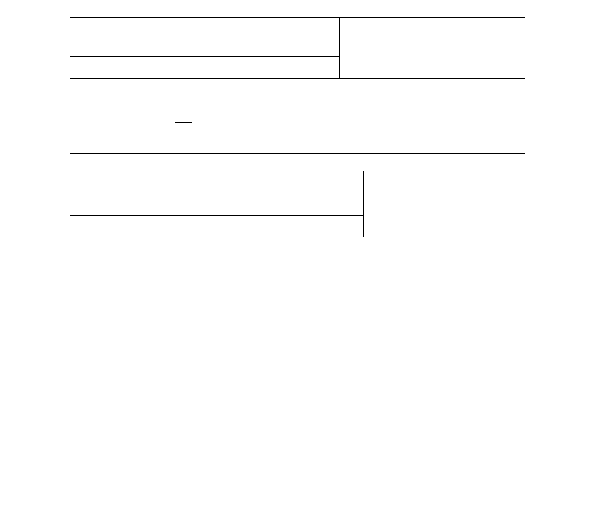
57
7 Renewable Generation Technologies
The following sections outline operational eligibility, system size, incentive calculation, application
documentation requirements, and metering requirements specific to SGIP renewable generation projects.
Additionally, all projects are subject to the general program requirements as outlined in Section 5.
7.1 Operational Eligibility Requirements
Generation technologies must meet or exceed a minimum operating efficiency requirement by meeting
either (1) waste heat utilization requirements or (2) minimum electric efficiency requirements as outlined
below.
Table 7.1a: Operational Eligibility Requirements for All Generation Technologies
All Generation Technologies
56
(1) Waste Heat Utilization
(2) Minimum Electric Efficiency
P.U. Code 216.6 (a) => T / (T + E
ELEC
) ≥ 5%
Electrical Efficiency = E / F
HHV
≥ 40%
P.U. Code 216.6 (b) => (E
ELEC
+ 0.5 x T) / F
LHV
≥ 42.5%
In addition, IC Engines, microturbines, and gas turbines must (1) meet the 60% minimum system
efficiency requirement
57
and (2) not exceed a NOx emissions standard of 0.07 lbs/MW-hr.
58
Table 7.1b: Operational Eligibility Requirements for IC Engines, Microturbines and Gas Turbines
IC Engines, Microturbines and Gas Turbines
(1) Minimum System Efficiency Standard
(2) NOx Emissions Standard
CHP System Efficiency = (E + T
WHR
) / F
HHV
≥ 60%
<= 0.07 lbs/MWhr
Electric Only System Efficiency = E/ F
HHV
≥ 40%
56
"Cogeneration" means the sequential use of energy for the production of electrical and useful thermal energy. The sequence can
be thermal use followed by power production or the reverse, subject to the following standards: (a) At least 5% of the facility's total
annual energy output shall be in the form of useful thermal energy; (b) Where useful thermal energy follows power production, the
useful annual power output plus one-half the useful annual thermal energy output equals not less than 42.5% of any natural gas and
oil energy input.
57
The minimum system efficiency shall be measured as useful energy output divided by fuel input in higher heating value. The
calculated minimum system efficiency shall be based on 100% load.
58
An emission credit for waste heat utilization may be used to adjust the final emissions determination of eligibility.

58
Table 7.1c: Operational Eligibility Requirements, Legend
Symbol
Description
T
The annual useful thermal output used for industrial or commercial process (net of any heat
contained in condensate return and/or makeup water), heating applications (e.g., space
heating, domestic hot water heating), used in a space cooling application (i.e., thermal
energy used by an absorption chiller)
E
ELEC
The annual electric energy made available for use, produced by the generator, exclusive of
any such energy used in the power production process
F
LHV
The generating system’s annual Lower Heating Value (LHV) non-renewable fuel
consumption
E
The generating system’s rated electric capacity as defined in Section 7.3, converted into
equivalent Btu/hr using the factor 3,414 Btu/kWh
F
HHV
The generating system’s Higher Heating Value (HHV) fuel consumption rate (Btu/hr) at
rated capacity
T
WHR
The generating system’s useful waste heat recovery rate (Btu/hr) at rated capacity
7.1.1 Locational Requirements – IC Engines
Internal combustion engine projects may be located in a county listed as a severe or extreme federal
nonattainment area for particulate matter (PM10 or PM2.5) or 8-hour ozone (O3) in the U.S.
Environmental Protection Agency Green Book for any of the three years prior to the SGIP application
date.
7.2 Capacity Factors
Generation systems are expected to operate at the following assumed capacity factors.
Table 7.2: Assumed Capacity Factors
Technology Type
Capacity Factor
Wind Turbine
25%
Other Generation Technologies – Dispatchable Resource
15%
All Other Generation Technologies – Baseload Resource
80%
Wind turbines are expected to operate at a 25% capacity factor. All other types of generation are
expected to operate at a capacity factor that aligns with its intended operation. Systems intended to
operate to offset a customer's ongoing baseload generation needs are expected to operate at an 80%
capacity factor. Systems intended to operate as a dispatchable generation resource to firm on-site
intermittent renewables, provide peak load shaving, and/or support flexible load are expected to operate
at a 15% capacity factor.

59
7.3 Sizing Requirements
The following table provides the sizing requirements for the applicable generation systems rated above 5
kW.
Table 7.3a: Sizing Requirements for the Applicable Generation Systems
Generation Technology
Incentivized Capacity
Sizing
Wind Turbines
Based on the highest electrical output from
the manufacturer’s power output curve for
wind speeds up to 30 mph including inverter
losses.
Systems less than 30 kW in capacity require
a minimum hub height of 25 feet. Systems 30
kW and greater do not have a height
limitation.
< 333 kW Up to 200% of
previous 12-month Annual
Peak Demand (1)
> 333 kW Up to 300% of
previous 12-month Annual
Peak Demand (1)
Pressure Reduction
Turbine (PRT)
Based on the average pressure drop across
and flow through the turbine, when flow
exists, as determined by historical flow and
pressure data from the previous year, if
available, or from an engineering estimate if
new construction or expanded load. Eligible
technology system rated capacity must be
substantiated with documentation from the
manufacturer.
Up to the Host Customer’s
Previous 12-Month Annual
Peak Demand (2)
Waste Heat to Power
Based on the average waste heat production
rate and temperature, when waste heat is
available, as determined by historical waste
heat and temperature data from the previous
year, if available, or from an engineering
estimate if new construction or expanded
load.
Microturbines – CHP
Using Directed Biogas: Based on full load net
continuous rated capacity of the packaged
prime mover/generator at ISO conditions.
Using On-site Biogas or Hydrogen: Based on
the average annual available fuel flow rate at
ISO conditions.
Gas Turbines – CHP
Internal Combustion
Engines – CHP
Linear Generators
Fuel Cells
Using Directed Biogas: Based on full load net
continuous rated capacity of the packaged
prime mover/generator at ISO conditions.
Using On-site Biogas or Hydrogen: Based on

60
the average annual available fuel flow rate at
ISO conditions.
Steam Turbines – CHP
Based on the rated capacity, which is the net
continuous power output of the packaged
prime mover/generator at the average
pressure and temperature of the steam
produced by a boiler.
Notes:
(1) Sites hosting existing generation, must also meet these sizing limits including both the capacity of
the proposed wind turbine and the capacity of any existing generators (excluding any backup
generators)
(2) If the site hosts existing generation, the combined capacity of the proposed and existing
generators (excluding any backup generators) must be no more than the Host Customer’s
maximum site electric load.
The following table provides the system sizing requirements for generation systems participating in Export
to Grid, Fuel Cell Net Energy Metering (FCNEM) Tariff, or the Renewable Energy Self-Generation Bill
Credit Transfer (RESBCT) Program.
Table 7.3b: Sizing Requirements for the Applicable Generation Systems
Application
Incentivized Capacity
Sizing
Export to Grid
59
Based on 100% Annual Energy
Consumption
Based on 125% Annual Energy
Consumption
Fuel Cells Participating in
FCNEM
60
Based on 100% Annual Energy
Consumption
Customers Participating
in RESBCT Tariff
61
7.3.1 System Sizing Limitations - Ineligible Host Customer Loads
The following loads cannot be considered when sizing a system:
• Any generation system where a customer has entered into contracts for distributed generation
services (e.g., distributed generation installed as a distribution upgrade or replacement deferral)
59
The incentivized capacity will be determined by dividing the annual electrical consumption at the site (in kWh) by 8760 hours and
the expected capacity factor of the technology as stated in Table 7.2.1.
60
Fuel cell customers who have been determined by the CPUC to achieve reductions in emissions of greenhouse gases pursuant to
subdivision (b) of Public Utilities Code § 2827.10 and meets the emissions requirements for eligibility for funding set forth in
subdivision (c) of Public Utilities Code Section 379.6 and has commenced operation on or before January 1, 2015.
61
Local government sites participating in the RES-BCT tariff must comply with the 5 MW cap per site.

61
and who are receiving payment for those services. This does not include Power Purchase
Agreements, which are allowed.
• Any portion of a Host Customer’s load that is committed to electric utility interruptible, curtailable
rate schedules, programs, or any other state agency-sponsored interruptible, curtailable, or
demand-response programs. For electric utility customers who are on an interruptible rate, only
the portion of their electric load designated as firm service is eligible for the SGIP. Customers
must agree to maintain the firm service level at or above capacity of the proposed generating
system for the duration of the applicable warranty period. Customers may submit a letter
requesting an exemption to the firm service rule if they plan to terminate or reduce a portion of
their interruptible load. Wind turbines need not abide by this portion.
• Publicly-owned or investor-owned gas or electricity distribution utilities, or any electrical
corporation (ref. Public Utilities Code Section 218) that generates or purchases electricity or
natural gas for wholesale or retail sales.
7.4 Renewable Fuel Eligibility Requirements
Eligible fuels are those that produce useful energy when undergoing combustion or a chemical reaction
and are classified as renewable.
62
Customers are required to use 100% renewable fuel for the lifetime of the project.
7.4.1 Directed Biogas Projects
Directed biogas projects must meet the following eligibility requirements and conditions:
• Directed renewable fuel must be produced within California and injected into a common carrier
pipeline.
• Any request to change the fuel provider during the 10-year fuel contract must be submitted to
the SGIP Program Administrator for approval.
63
7.4.1.1 Directed Biogas Project Renewable Fuel and Fuel Source Audits
Program Administrators or a third-party designee will conduct an annual audit of the renewable fuel
invoices for 10 years after the renewable fuel contract commences to verify renewable fuel consumption.
The audit and verification will use metered fuel consumption data for SGIP directed biogas projects,
invoices for directed renewable fuel purchases, documentation/verification of deliveries of directed
renewable fuel along the path from the original directed renewable fuel supply source to the SGIP
participant, and documentation to verify the amount and energy content of directed renewable fuel
injected into the path. The Program Administrator or a third-party designee will request all pertinent
62
For the purposes of the SGIP, renewable resources such as wind, pressure, waste heat, and water are not categorized as a fuel.
63
PAs shall respond to requests to change fuel supplier within 30 days.

62
information from the System Owner and/or renewable fuel provider at the completion of each year after
renewable fuel contract start date.
If invoices show that nominated renewable fuel deliveries fell below the generator’s fuel demand during
any one-year period, the SGIP Program Administrators may request that the System Owner refunds the
appropriate SGIP incentive amount and reserve the right to request a refund of additional costs (i.e., any
administrative or legal fees incurred).
SGIP Program Administrators will also conduct random no-warning spot checks of directed biofuel
sources. These spot checks will include verification of the biogas source, biogas flowrate, biogas cleanup
equipment necessary to make it ready for injection into the natural gas grid, and the biogas
interconnection equipment with the natural gas grid.
7.4.2 On-site Biogas Project Gas Quality Standard for IC Engines
On-site renewable biogas used in internal combustion engine projects must meet a 96% methane gas
quality standard. These projects will be required to self-certify that the equipment necessary to achieve
this requirement will be installed. Verification of installation will be completed during the on-site inspection
as well as during subsequent measurement and verification assessments.
7.4.3 Hydrogen Projects
Technologies operating on hydrogen are eligible if the hydrogen is produced at the project site or is
delivered to the project site by vehicle or dedicated pipeline.
Eligible hydrogen sources include:
• Non-combustion thermal conversion of biomass through gasification or pyrolysis. This does not
include the use of purpose grown crops as a source of biomass. Forest debris is an appropriate
(though not exclusive) fuel for this purpose.
• Electrolysis using 100% renewable electricity, as defined by the Renewables Portfolio Standard
• Hydropower, if the project is located on-site or if the electricity is directly connected to the project
via a dedicated line
If the renewable electricity is not generated on-site, the purchase program or load serving entity must
provide bundled Renewable Energy Credits to the electricity purchaser.
Hydrogen produced via steam methane reforming using either fossil or renewable fuel feedstocks are
ineligible for use in SGIP incentivized projects.

63
7.4.4 Pressure Reduction Turbines
Any steam turbine replacing a pressure reduction valve will be considered eligible under the pressure
reduction turbine category.
64
However, if the steam turbine is a straight power generator using
incremental fuel to create steam, the technology will be considered as a steam turbine, and any
incremental fuel used must be 100% renewable fuel.
7.5 Fuel Documentation Requirements for PBI
The following table outlines the data and verification requirements for directed and on-site renewable
generation PBI annual payments of systems 30 kW and larger.
64
Steam turbines replacing a pressure reduction valve consider the “waste steam” as an eligible fuel source and do not consider the
fuel used in the associated boiler.

64
Table 7.5: Fuel Documentation Requirements for PBI
Renewable Fuel
Type
Measurement and Documentation Requirements
Directed Biogas
Amount of directed renewable fuel consumed – reported monthly
65
Transportation Path and Energy Accounting – reported monthly
• Documentation from source showing the amount of directed biogas being
moved into the pipeline
• Any non-renewable gas added at the source must be identified
• Documentation from gas transmission system showing:
o Receipt of directed biogas
66
o Pipeline losses or fees paid in gas (not carried over)
o Positive or negative imbalances (carried over)
o Delivery of directed biogas to either another pipeline, storage
facility, or California receipt point
Gas Fuel Consumption – Reported quarterly
• Documentation from the gas utility matching the directed renewable fuel
receipts reporting the metered total energy input to the generator
On-Site Biogas
Amount of renewable fuel consumed (installation of a revenue grade meter
required)
67
– reported monthly
It is the responsibility of the System Owner to contract with a performance data provider (PDP) for a
minimum of five years and ensure that renewable fuel data is provided to the Program Administrator or
their designee monthly for five years. The PDP is responsible to supply the renewable fuel use
documentation and to ensure that the renewable fuel is reported to the Program Administrator or their
designee on a monthly and quarterly basis for five years.
All gas generation technologies must use 100% renewable fuel to be eligible for incentives. Annual PBI
payments will be adjusted according to the verified consumption of renewable fuel.
68
65
Must be provided through the SGIP database. Applicant or PDP is required to provide the source, path, and destination of the
renewable fuel. Reporting commences one month after the initial payment.
66
From source, storage, or other pipelines.
67
System Owner must provide make, model, specifications, and serial number of installed revenue grade gas meters.
68
Generation projects are also subject to applicable incentive limitations in Section 4.5.

65
8 Documentation Requirements
Scanned copies of original signature forms or electronically signed forms
69
are required for all SGIP
generated forms. This includes, but is not limited to, Reservation Request Forms, Proof of Project
Milestone Forms, Incentive Claim Forms, and all affidavits/attestations. The signature on any signed
document submitted to the Program Administrator shall create a valid and binding obligation of the party
executing (or on whose behalf such signature is executed) with the same force and effect as if such
signature page were an original thereof.
8.1 Reservation Requests
To request an incentive, an online RRF must be submitted with all required documents. Projects that
include multiple SGIP eligible technologies must submit separate applications for each technology.
Completed RRF and all required documents are submitted to the Program Administrator. Once a project
is assigned funding in a given step (on either a first-come or lottery basis), the Program Administrator
reviews the Reservation Request and supporting documents. Once the documentation has been
approved and eligibility requirements have been met, a Conditional Reservation Letter is issued for 3-step
applications and Confirmed Reservation Letter is issued for 2-step applications.
3-Step Applications
Upon approval of the Reservation Request Package, a Conditional Reservation Letter will be issued to
show that a specific incentive amount is conditionally reserved for the project. The letter will list the Proof
of Project Milestone (PPM) due date, Request for Proposal (RFP) due date (public entity projects), and
the Reservation Expiration date (18 months after the date of the Conditional Reservation Letter). All
reservations are conditional until the Program Administrator reviews and approves the PPM
documentation (to be received on or before the PPM due date).
2-Step Applications
Upon approval of the Reservation Request package, a Confirmed Reservation Letter will be issued. The
Confirmed Reservation Letter will list the reserved incentive amount and the Reservation Expiration date
(12 months after the date of the Confirmed Reservation Letter). Upon project completion and prior to the
Reservation Expiration date, the completed ICF must be submitted along with all the required
documentation to request an incentive payment.
Required Documentation for the Reservation Request
SGIP applications must provide a copy of the following:
69
All electronic signatures of SGIP generated forms must be accompanied by a signature audit page. SoCalGas only accepts One
Span electronic signatures for their SGIP generated forms.

66
Table 8.1: Reservation Request Requirements
Required Materials
1. Online Reservation Request Form (all projects)
2. Application Fee (non-residential projects)
3. Equipment Specifications (all projects except any energy storage system listed on the
SGIP Public Equipment List)
4. Proof of Utility Service (all projects)
5. Copy of Executed Contract or Agreement for Installation (all projects)
6. Load Documentation (all projects >10kW)
7. Preliminary Monitoring Plan (energy storage projects paired with on-site renewable
generators, projects subjected to PBI, and generation projects >=30 kW)
8. Minimum Operating Efficiency Worksheet w/Backup Documentation (generation
projects)
9. Proof of Adequate Fuel or Waste Energy Resource (generation projects)
10. Proof of Equity Eligibility (energy storage projects applying for an Equity or Equity
Resiliency Budget)
11. Proof of Resiliency Eligibility (Equity Resiliency projects, Resiliency Adder projects, and
projects opting into resiliency)
12. Proof of Coordination with Local Government and California Office of Emergency
Services (non-residential Resiliency Adder and Equity Resiliency projects)
1. Online Reservation Request Form (all projects)
All Applicants are required to complete the online RRF. The RRF is used to provide project details,
contact information, and signed declarations. Residential energy storage projects must also fill out the
Residential Energy Storage Eligibility Affidavit portion of the RRF.
As part of the RRF, the project Host Customer must attest that an Energy Efficiency Audit (EEA)
70
has been performed for the project site and they received and reviewed the findings of the audit.
For storage systems not pursuing resiliency, the Host Customer must also attest on the RRF that
their Developer has notified them that the system is not intended for backup capability.
The RRF must be signed by the Applicant, Developer, Host Customer, and System Owner (if not
Host Customer). A copy of the signed document must be uploaded to the online application database
70
An Energy Efficiency Audit (EEA) report issued within the past five years. A Title 24 energy efficiency compliance report issued
within the past three years may also be used in lieu of an Energy Efficiency Audit.

67
and the information contained on the signed copy of the RRF must match the information provided on
the online RRF.
2. Application Fee (non-residential projects)
The application fee for non-residential project applications is equal to 5% of the requested incentive
amount, payable by check, cashier check, or money order, and should reference the project by site
address.
71
The application fee is the only required document that must be mailed directly to the
Program Administrator.
72
After a project is assigned to an incentive step, if the application fee is not
already received, the Program Administrator will send out an Application Fee Invoice Notice with
specific instructions on how and where to mail the application fee. The application fee check must be
mailed within seven calendar days of the Application Fee Invoice Notice. If the check is not mailed
within seven calendar days, the project may be cancelled. Application fee checks returned by the
financial institution without payment may result in cancellation of the application.
The application fee will be refunded upon completion and verification of the installed SGIP project.
Prior to project completion, application fees are non-refundable once Confirmed Reservation has
been issued.
73
All forfeited application fees will be allocated to the Program Administrator’s current
incentive step.
Wind Projects Only
Prior to project completion, application fees are non-refundable once a Confirmed Reservation has
been issued, unless the Host Customer subsequently cancels the project, requests a refund, and
certifies to the Program Administrator Working Group that it was unable to obtain a permit required for
the installation and operation of the project or that the utility required installation of distribution
upgrades that rendered the project financially unfeasible. In this case, the Program Administrator
Working Group shall approve such requests unless it determines that the original Confirmed
Reservation was obtained in bad faith or without the Host Customer having a reasonable expectation
of obtaining the required permit or a financially feasible interconnection of the project.
3. Equipment Specifications (all projects except any energy storage system listed on the SGIP Public
Verified Equipment List)
Electrochemical Energy Storage Projects
Equipment and/or component pairings that have been evaluated and deemed eligible for participation
in the program can be found on the SGIP Public Verified Equipment List at www.selfgenca.com. For
projects using equipment and/or component pairings not yet evaluated by the Technical Working
Group, manufacturer equipment specifications for all major components of the system, such as the
71
Application fees are specific to an application, not a site. If the same site reapplies to the program, they will need to submit a new
application fee.
72
A single application fee check for each non-residential project is required.
73
Application fees will not be altered due to project changes that may result in a different incentive.

68
storage component, as well as the inverter, DC-DC converter, controller, and/or additional system
components when applicable, are required. Rated capacity (kW), energy capacity (kWh), and round-
trip efficiency
74
for the storage system must be provided. Equipment specifications may be submitted
to any PA via email to the contact information listed on www.selfgenca.com.
DC/AC systems must provide all specifications necessary to calculate the rated capacity and energy
capacity, such as:
• Duration of discharge (hours)
• DC dischargeable amp-hour capacity, associated with the duration of discharge specified,
including all losses and ancillary loads (such as power conditioning and thermal
management)
• Nominal voltage (V
DC
)
• Inverter CEC-AC efficiency
• DC-DC converter efficiency
• Inverter continuous power output rating (kW)
• The continuous maximum power output capability of the system.
75
For DC systems, this is
rated in DC, and for AC systems, this is rated in AC.
HVAC-integrated S-TES Projects
Must provide the TES system equipment specifications, HVAC system equipment specifications
identifying the SEER and tonnage of the HVAC unit and the climate zone in which the project is
located. Must provide the TES system’s maximum HVAC compressor runtime and its interval period
during system’s discharge duration.
Refrigeration TES Projects
Must provide TES system equipment specifications, refrigeration system equipment specifications,
the Refrigeration TES kW Worksheet and backup documentation of any site-specific conditions, if
relevant.
L-TES Projects
Must provide TES system equipment specifications, chiller system equipment specifications, cooling
tower equipment specifications (if applicable), the L-TES kW/kWh-AC Offset Worksheet that has
been populated by the calibrated building simulation model output, a copy of the building simulation
model inputs and output, and backup documentation of any site-specific conditions, if relevant. If the
simulation model used is proprietary, substantiation must be provided to show that the model is
74
AC-AC for AC systems and DC-DC for DC systems
75
Maximum continuous output may be determined by the calculated maximum continuous discharge power of the energy storage
system or by the continuous rated power output of the inverter depending on which is less.

69
compliant with ANSI/ASHRAE Standard 140-2017 and ASHRAE Standard 90.1 2016/2019 Appendix
F.
Generation Projects
Manufacturer equipment specifications for all major components of the system are required, in
addition to the nameplate capacity, rated capacity (kW) efficiency, and, if necessary, fuel
consumption and waste heat recovery rate of the system.
Proof of power factor eligibility is also required for microturbines, internal combustion engines, gas
turbines, and stream turbine CHP applications (where applicable) and must include self-generating
facility design specifications and/or manufacturer’s specifications which show that the system will be
capable of operating between 0.95 PF lagging and 0.90 PF leading.
4. Proof of Utility Service (all projects)
Participation in the SGIP is restricted to IOU customers who are located in PG&E, SCE, SoCalGas, or
SDG&E service territories and physically connected to the electric utility transmission and distribution
system. All applications in SCE, SoCalGas, and SDG&E service territories must include a complete
copy of a recent electric utility bill (all pages), indicating the account number, meter number, site
address, and Host Customer name.
76
For new construction, the Host Customer must submit
confirmation from the serving utility that their site is within the Program Administrator’s service
territory. Customers applying in PG&E
77
and SoCalGas territory must also submit a copy of a recent
gas utility bill. CSE may require the Authorization to Receive Customer Information form for any
project at any time during the application process if additional utility information must be verified in
order to approve the application.
Multifamily Projects
Proof of number of and types of accounts benefiting from the incentivized system must be provided.
Projects interconnecting under a VNEM tariff must submit a VNEM Generation Credit Allocation
Request Form to determine the project’s primary use case (residential or non-residential). See
Section 3.3 for more information on how multifamily projects are classified. If the primary use case is
determined to be residential, all benefiting tenant accounts will be required to be enrolled in an SGIP-
eligible TOU rate.
78
Projects interconnecting under a VNEM tariff applying for Equity Resiliency incentives, the Resiliency
Adder, or the increased discharge duration for Resiliency systems must also demonstrate 1) the
applicable utility’s VNEM tariff allows installed storage to serve on-site load; and (2) the Applicant
76
A utility bill may be required at PG&E’s discretion.
77
PG&E customers are only required to submit a copy of a recent gas utility bill if not receiving electricity from PG&E.
78
For projects located in front of the customer’s electric meter, each customer may be automatically transferred to an SGIP-eligible
TOU rate (if one is available to them) by the electric IOU, if one was not selected at interconnection.

70
intends to use a switching and isolation technology arrangement allowed under Rule 21 at the time
the of application to provide for discharging the battery to serve on-site load and to island.
5. Executed Contract and/or Agreement for System Installation (all projects)
A copy of the executed contract for purchase and installation of the system, and/or alternative System
Ownership Agreement (such as a Power Purchase Agreement) is required. The contract/agreement
must be legally binding and clearly spell out the terms and scope of work. Purchase and/or
installation agreements must also include system equipment and eligible system costs. All
contracts/agreements must be signed by appropriate representatives (Host Customer, Installer,
and/or System Owner) who are a party to the agreements of the SGIP reservation.
• As part of the Executed Contract, all systems are required to include a minimum 10-year
service warranty (wind turbine systems must have a minimum 20-year service
warranty). A service warranty ensures proper maintenance and continued project
performance. The service warranty must cover the system maintenance to include (but not
limited to) system support, problem diagnosis, on-site repair, and preventative maintenance.
The warranty should also include language to guarantee the continued performance of the
system over the warranty period. The System Owner must provide proof of warranty and
maintenance contract and specify the warranty and maintenance contract start and end
dates. An exception to the service warranty can occur when a developer has declared
bankruptcy or gone out of business, and provided that the CPUC has approved the exception
through the disposition of a Tier 2 Advice Letter submitted by the PAs.
• For projects claiming the ITC for equipment purchased after December 31, 2021: Proof
of purchase dated after December 31, 2021 for the energy storage equipment and its main
components (battery, inverter, controls) is required.
3-step applications may submit the executed contract during the PPM stage.
6. Load Documentation (all projects >10kW)
For projects applying in CSE and SoCalGas territories, applications for technologies that discharge
electricity to the on-site load must include documentation of the previous 12 months of electric
consumption including maximum demand and kWh consumption to confirm that the participating
generation system meets the program sizing requirements. Electric utility customers of SCE and
PG&E are not required to submit their 12-month electric consumption and demand data.
SDG&E customers are also required to submit an Authorization to Receive Customer Information
form, signed by the utility customer of record that authorizes CSE to access utility account information
for systems greater than 10 kW.

71
If the system is being sized based on new or future load growth (i.e., new construction or load growth
due to facility expansion or other load growth circumstances), applications must include an
engineering estimate with appropriate substantiation of the site’s annual peak demand forecast.
Suggested methods of demonstrating load growth include Application for Service with corresponding
equipment schedules and single-line diagram; building simulation program reports such as eQUEST,
EnergyPlus, EnergyPro, DOE-2, and Visual DOE; or detailed engineering calculations.
Energy Storage Projects
Projects applying to the Equity Resiliency Budget or are otherwise receiving the Resiliency Adder for
a system that is sized above peak load necessary due to modular component sizes to accommodate
the customer’s peak load must demonstrate proof of this need. An ad-hoc letter explaining the need
for the larger system size to cover the customer’s previous 12-month annual peak demand must be
provided.
Large Thermal Energy Storage Projects
Must provide pre-installation monitoring data as outlined in Section 9.1.4 (Large TES Monitoring
Requirements) during periods that occur during any 30 consecutive day period within the designated
IOU summer period that contains at least nine days with a peak ambient air temperature of 90ºF or
above, or within 10ºF of the peak ambient temperature in the TMY3 file for the project, with at least
three of the peak temperature days being consecutive. Pre-monitoring should occur no greater than
18 months prior to the installation of the L-TES system.
7. Preliminary Monitoring Plan (energy storage projects paired with on-site renewable generators,
projects subjected to PBI, and generation projects >=30kW)
Examples and a blank preliminary monitoring plan template can be downloaded from the
www.selfgenca.com website.
Energy Storage Projects
The preliminary monitoring plan should demonstrate the following components:
• Description of the proposed SGIP system: Include a description of the system with an
overview of the energy services to be provided by the system to the project site; the major
components making up the system; and the intended operation of the system (e.g., demand
charge management of the facility or specific end-use equipment, TOU energy arbitrage,
shifting excess generation). Include photos and/or diagrams of the system if available.
• Description of the backed-up loads: Include a description of the loads at the site that will
be backed up by the energy storage system.
• Description of the metering system and metering approach: Include an overview of the
performance data to be collected and a simplified layout of the system showing major

72
components and location of the proposed metering points and data to be collected at those
points is required.
• Description of the approach to be used for collecting, storing, and transferring the
necessary performance data:
o The reasoning behind the selected metering points (for example, if electrical energy
performance data is to be collected)
o Frequency with which the data is to be collected (e.g., 15-minute intervals)
o Data storage capability and approach for transfer of data (e.g., cell modem)
o For all new non-residential systems, the frequency of reporting to PDP (e.g., daily,
weekly), which could also include frequency for reporting of data to Program
Administrators (e.g., monthly)
• Identification of the metering system components by performance data type (including
manufacturer and model number):
o Electrical metering equipment (AC meters must meet the criteria for the applicable
project type (see Section 9)
o Thermal energy metering equipment
o Data acquisition (i.e., logger) system
• Systems Pairing with On-Site Renewable Generators: Energy storage systems paired
with on-site renewable generators must provide a description of:
o The anticipated charge and discharge schedule of the system demonstrating that the
system complies with ITC operational requirements or will be charged at least 75%
from renewables.
o The metering that will be used to verify that the system is being charged from
renewables.
o The ability to provide data to verify operation in the event of an audit.
Renewable Generation Projects
The preliminary monitoring plan should demonstrate the following components:
• Description of the proposed SGIP system:
o Include a description of the system with an overview of the energy services to be
provided (e.g., generation, waste heat recovery, storage) by the system to the project
site; the major components making up the system; and the general operating
schedule of the system (e.g., is it 24x7x365 or 10x6x365); the operating schedule is
required to distinguish the system’s intended operation as either a dispatchable or
baseload generation resource. Include photos and/or diagrams of the system if
available.

73
o Break out subsystems such as waste heat recovery systems to provide context for
thermal energy metering systems. Provide similar descriptions for other important
subsystems such as energy storage when combined with wind systems.
o Include a description of the existing load at the site and identification of the sources
of the fuel that would be displaced by operation of the SGIP system (i.e., electricity
provided by XYZ utility or natural gas provided by ABC utility) and photos of the
interface locations where the SGIP system would be located to displace the load.
• Description of the metering system and metering approach:
o Include an overview of the performance data to be collected (e.g., electrical, useful
thermal energy, fuel consumption) and a simplified layout of the system showing
major components (e.g., generator, waste heat recovery, storage) and location of the
proposed metering points and data to be collected at those points (e.g., electrical,
flow, temp, fuel) is required.
o Two-Step Applications will include (as part of their Reservation Request) a Proposed
Monitoring Plan as outlined in Section 8.2.4.
8. Minimum Operating Efficiency Worksheet with Backup Documentation (generation projects)
The Minimum Operating Efficiency Worksheet (MOEW) is used to evaluate a project’s technical
ability to meet the following requirements:
• Minimum operating efficiency requirement which can either be satisfied by meeting:
o Waste Heat Utilization, or
o Minimum Electrical Efficiency Requirements
• Thermal Load Coincidence
• CHP System Efficiency and NOx Emission Qualification
• Electrical Load Coincidence (Electrical Export Eligibility)
Minimum Operating Efficiency Calculations
The MOEW is a spreadsheet used to evaluate the project’s estimated minimum operating
efficiency over 10-years. Additionally, the MOEW verifies the first-year minimum operational
efficiency for Electric-only fuel cells and linear generators. All applications proposing renewable-
fueled technologies must provide backup documentation along with the MOEW. CHP systems
must additionally include engineering calculations with documented assumptions regarding the
site’s thermal load. All assumptions, backup documentation, hand calculations, models (with
inputs and outputs), and custom spreadsheets used to develop the forecasts must be included in
the documentation. Forecasts based solely on “professional experience” or subjective
observation will be rejected.
Specifically, the following applicable documentation must be provided:

74
• Generator & Thermal System Description: The application must include the performance
and capacity specifications for the proposed CHP system and all thermal system equipment
that the CHP system interacts with or serves. This includes but is not limited to the generator
system, heat recovery system, heat exchangers, absorption chillers, boilers, furnaces, etc. In
addition, a thermal process diagram must be provided as part of the documentation package
that shows the configuration of the generator(s), heat recovery system, pumps, heat
exchangers, thermal load equipment, and the working fluid flow and temperatures in/out of
each piece of major equipment at design conditions.
• Forecast of Generator Electric Output: The MOEW must include a forecast of the monthly
generator electric output (kWh/month) for a 12-month period. The generator electric output
forecast must be based on the operating schedule of the generator, historical or site electric
load forecast, and maximum/minimum load ratings of the generating system, exclusive of any
electric energy used in ancillary loads necessary for the power production process (e.g.,
intercooler, external fuel gas booster).
• Forecast of Generator Thermal Output: The application must include a forecast of the
monthly generator thermal output (Btu/month) for a 12-month period. The generator thermal
output forecast must be based on the electric output forecast of the generating system and
the waste heat recovery rate specifications of the system.
• Forecast of Generator Fuel Consumption: The application must include a forecast of the
generating systems monthly fuel consumption (Btu/month) for a 12-month period. The
generator’s fuel consumption forecast must be based on the generating system electric
output forecast and the systems fuel consumption specifications.
• Forecast of Thermal Load Magnitude: The application must include a monthly Thermal
Load forecast (Btu/month) for a 12-month period for the Thermal Load served by the CHP
system. The forecast must be based on engineering calculations, thermal system modeling,
historical fuel billing, measured data or a combination of these methods. The Thermal Load
forecast must be independent of the generator operation forecast. If historical natural gas or
other fossil fuel consumption records (e.g., billing records) are used, the combustion
efficiency of the natural gas or fossil fuel fired equipment that is being displaced must be
included. Historical fuel consumption must be discounted to account for equipment Thermal
Load that will not be displaced by the prime mover’s thermal energy.
• Forecast of Useful Thermal Output: The useful thermal output of the CHP system will be
the lesser of the Thermal Load forecast, or the prime mover’s thermal output coincident with
the Thermal Load. The useful thermal output is the value used in calculating the Public
Utilities Code 216.6 requirements.
Thermal Load Coincidence

75
Thermal load coincidence is calculated in the worksheet by comparing the waste heat recovered
to the thermal load on an annual basis. The backup documentation listed above for the forecast
of generator thermal output and forecast of thermal load magnitude will be sufficient to meet this
operating efficiency requirement.
CHP System Efficiency and Proof of Nitrogen Oxides (NOx) Emission Qualification
Applications must include documentation substantiating that the generating system meets or exceeds
the 60% minimum system efficiency and NOx emissions are at or below the applicable emission
standard. One of the following documents must be included to determine the NOx emissions
(lb/MWh) of the proposed system:
• Manufacturer emission specifications based on factory testing using California Air Resources
Board (CARB), EPA, or local air district test methods for the proposed generating system as
configured for the site
• CARB distributed generation certification
• Emission engineering calculations for the proposed generating system as configured for the
site
Conversion of emissions concentration (ppm) to production-based emissions rates (lb/MWh) shall use
the method found in Appendix B of this Handbook. Units that do not pass the emission standard may
use emission credits. If the application claims NOx emissions credits for their waste heat utilization
emission, credit calculation documentation based on the amount of waste heat utilized over a 12-
month period must be provided.
Electric Load Coincidence (Electrical Export Eligibility)
The application must include the monthly electrical load for the previous 12 months. This information will
be used in the MOEW to determine electrical load coincidence with electrical generation on an annual
basis. If the generator is eligible to export electricity to the grid, the electrical generation will be compared
to 125% of electrical load on an annual basis.
9. Proof of Adequate Fuel or Waste Energy Resource (generation projects)
• On-site biogas projects (including on-site hydrogen) must include an engineering survey
or study confirming the renewable fuel (i.e., adequate flow rate) and the generating system’s
average capacity during the term of the project’s required permanency period.
• Biogas projects utilizing directed renewable fuel or hydrogen delivered via vehicle or
dedicated pipeline must include documentation of the forecasted fuel consumption of the
generator over the life of project.
• Proposed pressure reduction turbine applications must include an engineering survey or
study confirming adequate temperature, pressure, and flow within the piping system, and the

76
generating system’s rated capacity. The rated capacity must be based upon the average
pressure drop across and flow through the turbine, when flow exists, as determined by
historical flow and pressure data from the previous year if available, or from an engineering
estimate if new construction or expanded load. Additionally, the survey or study must show
that the capacity factor for the proposed project will be greater than or equal to 40% based
upon conditions over the course of a full year, or from an engineering estimate for future
conditions.
• Proposed waste heat to power applications must include an engineering survey or study
confirming adequate waste heat production rate and temperature, and the generating
system’s rated capacity. The rated capacity must be based upon the average waste heat
production rate and temperature, when waste heat is available, as determined by historical
waste heat and temperature data from the previous year if available, or from an engineering
estimate if new construction or expanded load. Additionally, the survey or study must show
that the capacity factor for the proposed project will be greater than or equal to 40% based
upon conditions over the course of a full year, or from an engineering estimate for future
conditions.
• Proposed wind projects must include an engineering survey or study evaluating the annual
average wind speed at the hub height of the wind turbine. The study must confirm that the
average annual wind speed is equal to or greater than 10 mph (4.5 m/s). The wind resource
can be verified using wind resource maps from NREL or the CEC and standard formulas for
correcting differences in tower heights or by gathering wind data on site at the turbine’s
proposed hub height for one year.
For wind projects less than 30 kW in capacity, wind speed data must be collected at the
turbine’s proposed on-site location and hub height for a minimum of 60 days, and a third
party must correlate the data using local annual wind speed data (gathered at an airport and
averaged over the past three years) to determine if the average annual wind speed is greater
than 10 mph.
10. Proof of Equity Eligibility (energy storage projects applying for an Equity Budget)
• Certification of Tax-Exempt Status – Government (Non-Residential Equity Budget): State
and local government and non-profit entities are required to submit verification of their tax-
exempt status.
• Proof of Non-Profit Registration (non-profit organizations): Customers qualifying for the
Equity Budget must provide proof of registration and good standing with the California
Secretary of State as a domestic non-profit entity.
• Proof of Eligibility under Proposition 39 or an Accredited Institution – Educational
Institutions (Non-Residential Equity Budget): For educational institutions, Applicants must

77
submit documentation proving eligibility under the California Energy Commission’s
Proposition 39 Program
79
, or which confirm they are an accredited educational institution.
• Small Business Affidavit – Small Business (Non-Residential Equity Budget): Application
documentation must include a signed affidavit affirming that the Host Customer is a business
or manufacturer, including affiliates, with average annual gross receipts of $15 million or less
over the last three tax years.
• Deed Restriction or Regulatory Agreement – Multifamily (Residential Equity and Equity
Resiliency Budgets): For a multifamily residential complex financed with low-income housing
tax credits, tax-exempt mortgage revenue bonds, general obligation bonds, or local, state, or
federal loans or grants, a deed restriction on the property, or a regulatory agreement signed
and executed between the Property Owner/Developer and entity issuing financing must be
submitted.
• SGIP Multifamily Low-Income Housing Documentation Cover Sheet – Multifamily
(Residential Equity and Equity Resiliency Budgets): To clearly outline how a project achieves
Public Utilities Code Section 2852 low-income eligibility, Applicants are required to submit a
cover sheet identifying key details within the deed restriction or regulatory agreement such
as, but not limited to, property owner name, public entity/non-profit agency name, expiration
date of low-income documentation, rent restriction description, and percent of households
with incomes at or below 60% of the area median income. This will allow Program
Administrators to determine more accurately and efficiently eligibility.
• Proof of Income Qualification – Single Family (Residential Equity and Equity Resiliency
Budgets *includes Indian Country and electric-pump well projects): Provide documentation
showing the Host Customer’s household income is 80% of the area median income or less
based upon a copy of the most recently available federal income tax documentation. Area
median income is subject to annual changes based upon Housing and Urban Development’s
income guidelines.
80
Contact your Program Administrator for instructions on how to submit
the appropriate documents for your application.
A copy of the customer’s most recent 1040 form should be provided. In the event the
customer did not file a 1040 or comparable document to the IRS, the customer should work
with the Program Administrator to determine an acceptable alternative document to prove the
household income for their project.
79
Proposition 39 eligibility guidelines can be found at http://www.energy.ca.gov/efficiency/proposition39/.
80
Area Median Income is subject to annual changes based upon Housing and Urban Development's income guidelines
(https://www.huduser.gov/portal/datasets/il.html).

78
• Proof of Public Utilities Code Section 2852 Compliance – Single Family (Residential
Equity and Equity Resiliency Budgets): To demonstrate compliance with Public Utilities Code
Section 2852,
81
Applicants may submit a copy of a resale restriction or equity sharing
agreement for which the homeowner does not receive a greater share of equity than
described in paragraph (2) of subdivision I of Section 65915 of the Government Code. The
resale restriction or equity sharing agreement must be between the homeowner and a public
entity or a qualifying non-profit affordable housing provider. Additionally, a presumed resale
restriction may also be demonstrated to meet the resale restriction eligibility requirement,
such as single-family homes located in IRS-defined Qualified Census Tracts
82
and other
designated areas eligible for the Single-Family Affordable Solar Homes (SASH) program.
• Copy of MASH, SOMAH, SASH, or DAC-SASH Reservation Letter – Low-income
(Residential Equity and Equity Resiliency Budgets): Customers must provide a copy of their
incentive reserved status of the MASH, SOMAH, SASH, or DAC-SASH program that they are
eligible for the program.
• Proof of Indian Country Qualification (all Equity Budgets): A Native American tribal card or
official document must be provided to be eligible for the expanded DAC requirement.
• Proof that at least 50% of census tracts served are DACs or low-income communities
(non-residential Equity Budget): Customers have the burden of providing any information that
demonstrates a facility’s eligibility.
11. Proof of Resiliency Eligibility (Equity Resiliency projects, Resiliency Adder projects, and projects
opting into resiliency)
Customer Resiliency Attestation - Energy Storage Projects
83
(Equity Resiliency projects, Resiliency
Adder projects, and projects opting into resiliency):
A copy of the Customer Resiliency Attestation must be submitted including the following information
to be provided by the Developer:
• Provide an estimate of how long a project’s fully charged battery will provide electricity for the
relevant facility average load during an outage.
• Indicate whether a project’s critical loads can and will be isolated.
• Provide an estimate of how long the project’s fully charged battery will provide electricity to
critical uses during an outage.
81
As described in subparagraph (c) of paragraph (3) of subdivision (a).
82
Qualified Census tracts are defined by Internal Revenue Code Section 143(j)(2) as “a tract in which 70% or more of the families
have income which is 80% or less of the statewide median family income” https://www.huduser.gov/portal/sadda/sadda_qct.html
83
A blank questionnaire form and optional Resiliency Attestation Tool can be downloaded from the Forms and Documents page of
www.selfgenca.com. The Host Customer and Developer must sign the document after filling out the questionnaire.

79
• Provide an estimate of how long the project can operate in less-than favorable circumstances,
such as if an outage occurs when the battery has been discharged or during the winter (if paired
with solar).
• Summarize information given to the customer about how the customer may best prepare the
storage system to provide backup power in the case of a PSPS event announced in advance.
• Attest to the truth of the information provided.
• Provide an attestation from the customer indicating that they received this information prior to
signing a contract.
Proof of Critical Facilities (non-residential Equity Resiliency Budget and Resiliency Adder projects): The
Program Administrators may request for proof of the type of critical facility the customer is claiming. The
critical facilities that may require to submit proof are (including but not limited to):
• Cooling center designated by state, local, or tribal government
• Emergency operations center
• Location designated by an IOU to provide assistance during PSPS events
Renewable Generation Projects
For generation projects applying for the Resiliency Adder incentive, it is required that generation:
• Provide an estimate of how long a project’s generation system will provide electricity for the
relevant facility average load during an outage.
• Indicate whether a project’s critical loads can and will be isolated.
• Provide an estimate of how long a project’s generation system will provide electricity to
critical uses during an outage.
• Provide an estimate of how long the generation system can operate in less-than favorable
circumstances.
• Summarize information given to the customer about how the customer may best ensure
operation of the generation system in the case of a PSPS event announced in advance.
• Attest to the truth of the information provided.
• Provide an attestation from the customer indicating that he or she received this information
prior to signing a contract.
• Demonstrate that an Authority Having Jurisdiction has approved plans showing that the
system can operate in islanded mode, has inspected the system after installation, and has
authorized operation.
Proof of Electric-Pump Well – Single Family (Equity Resiliency Budget projects): Each electric pump well
customer must submit the SGIP Electric Pump Well Attestation
84
that confirms the following:
84
Downloadable on Forms and Documents page of www.selfgenca.com.

80
• Site is the customer’s primary residence.
• The customer does not have access to a public water source.
Documentation will also be requested at the discretion of the Program Administrator to verify the eligibility
of the equipment. Acceptable documentation to verify eligibility may include (but is not limited to):
• Photographs of the pump and motor
• Photograph of the home and well
• A photograph showing the meter behind which the pump is installed and/or copy of the
electric bill
• The pump is serving the residential load and is assigned a residential tariff
If a Program Administrator is unable to reasonably verify the presence and eligibility of the electric pump
well, the project may be required to undergo an on-site inspection rather than be subjected to an
inspection sampling by Developer.
Proof of Medical Baseline or Notification of Serious Illness or Condition – Single Family (Equity Resiliency
Budget projects): Each Medical Baseline customer and/or customer notifying their utility of a serious
illness or medical condition that could become life-threatening in the event of an outage, must submit the
SGIP Medical Baseline Attestation(s) that confirms the following:
o Equity Resiliency Budget incentive will be used for energy storage equipment
installed at the customer’s primary residence; and
o Customer is self-certifying that they have a serious illness or condition that could
become life-threatening if service is disconnected.
The following documents may also be required to be submitted to show proof of Medical Baseline or
Notification of Serious Illness or Condition:
• Documentation demonstrating that the customer has notified their electric utility that they
have a serious illness or condition that could become life-threatening if service is
disconnected
• Documentation from the electric utility demonstrating participation in a Medical Baseline
program
12. Certification/Proof of Coordination with Local Government and California Office of Emergency
Services (Non-residential Equity Resiliency and Resiliency Adder applications)
Non-residential customers must demonstrate that they are coordinating with their local government
and the California Office of Emergency Services if applying for Equity Resiliency or for a Resiliency
Adder Incentive. Customers that cannot demonstrate this, will have their application deprioritized in
favor of Applicants that can provide proof.

81
8.2 Proof of Project Milestone
Completed PPM Form and all required documents are due within 90 calendar days of the Conditional
Reservation date for non-public entities, and within 240 calendar days for public entities (copy of RFP due
within 90 days).
Completed PPM Form and all required documents are submitted to the Program Administrator. The
Program Administrator reviews the PPM documents. Once the documentation has been approved, a
Confirmed Reservation Letter is issued.
The Confirmed Reservation Letter will list the reserved incentive amount and the Reservation Expiration
date (18 months after the date of the Conditional Reservation Letter). Upon project completion, and no
later than the Reservation Expiration date, the completed Incentive Claim Form (ICF) must be submitted
along with all the required documentation to request an incentive payment.
Required Documentation for Proof of Project Milestone
Three-Step Applications must provide a copy of the following:
Table 8.2: Proof of Project Milestone Requirements
Required Materials
1. Online Proof of Project Milestone Form (all Three-Step projects)
2. Copy of RFP or Equivalent (public entity projects)
3. Copy of Executed Contract or Agreement for Installation (all Three-Step projects)
• Includes Required Warranty Documentation
4. Proposed Monitoring Plan (generation projects >=30kW)
5. Proof of Fuel Contract and Documentation (generation projects)
1. Online Proof of Project Milestone Form (all Three-Step projects)
85
The Online PPM Form must identify if there are changes from the information that was presented in
the RRF. If there have been changes from what was submitted in the RRF, the PPM Form must be
signed by the Applicant and representatives with signature authority for both the System Owner and
Host Customer (if not Host Customer). The online form must identify updated project information
including the installation contractor’s name, telephone number, and contractor license number. All
systems must be installed by an appropriately licensed California contractor in accordance with rules
and regulations adopted by the State of California Contractors State License Board (CSLB).
86
85
Not required for Two-Step Applications as part of the Reservation Request Package.
86
List of appropriate CSLB classifications can be found at www.selfgenca.com under the ‘Forms and Documents’ page.

82
If there have been no changes to the application from what was approved in the Conditional
Reservation, a signed PPM Form is not required.
2. Request for Proposals Documentation (public entity projects)
Include Notice to Invite Bids, or similar solicitation issued for the installation, lease, and/or purchase
for systems proposed for the SGIP. The RFP must include sufficient project details such as the scope
of work, schedule, terms, budget, and/or system components desired. For Public Entities not issuing
an RFP, alternative documentation such as an executed letter of intent to engage with a contractor on
the Host Customer letterhead, an executed contract/agreement for system installation/lease, an
equipment purchase order, or alternate System Ownership Agreement must instead be submitted
within 90 calendar days of the date the Conditional Reservation Letter. PPM documentation must
then be submitted within 240 days of the date of the Conditional Reservation Letter.
3. Executed Contract and/or Agreement for System Installation (all projects)
See section 8.1.1 #5 for more details.
4. Proposed Monitoring Plan (generation projects >=30 kW)
The proposed monitoring plan should demonstrate the following components:
• Description of the proposed SGIP system(s): Description of the system(s) with an
overview of the energy services to be provided (e.g., generation, waste heat recovery,
storage) by the system(s) to the host site; the major components making up the system(s);
and the general operating schedule of the system(s) (e.g., is it 24x7x365 or 10x6x365); the
operating schedule is required to distinguish the system’s intended operation as either a
dispatchable or baseload generation resource. Include photos of the system(s) if available.
Break out subsystems such as waste heat recovery systems to provide context for thermal
energy metering systems. Provide similar descriptions for other important subsystems such
as energy storage when combined with wind systems.
A description of the existing load at the site and identification of the sources of the fuel that
would be displaced by operation of the SGIP system(s) (i.e., electricity provided by XYZ utility
or natural gas provided by ABC utility) and photos of the interface locations where the SGIP
system would be located to displace the load.
• Description of the metering system and metering approach: An overview of the
performance data to be collected (e.g., electrical, useful thermal energy, fuel consumption)
and a simplified layout of the system showing major components (e.g., generator, waste heat
recovery, storage) and location of the proposed metering points and data to be collected at
those points (e.g., electrical, flow, temp, fuel) is required.

83
• Description of the approach to be used for collecting, storing, and transferring the
necessary performance data:
o The reasoning behind the selected metering points (for example, if useful thermal
energy data is to be collected)
o Frequency with which the data is to be collected (e.g., 15-minute intervals)
o Data storage capability and approach for transfer of data (e.g., cell modem) and
frequency of reporting to PDP (e.g., daily, weekly), which could also include
frequency for reporting of data to Program Administrators (e.g., monthly)
• Identification of the metering system components by performance data type (including
manufacturer and model number):
o Electrical metering equipment (AC meters must be listed on the CEC’s list of Eligible
System Performance and Revenue Grade Meters to be found on
https://solarequipment.energy.ca.gov/Home/MeterList
o Thermal energy metering equipment
o Fuel consumption metering equipment
o Data acquisition (i.e., logger) system
5. Proof of Fuel Contracts and Documentation (generation projects)
• Copy of Executed Renewable Fuel Contract (directed renewable fuel and hydrogen
delivered via dedicated pipeline or vehicle): The Contract should at a minimum include term
(minimum of 10 years), cost, amount of renewable fuel injected or delivered monthly for the
length of the contract, address of renewable fuel facility, location of pipeline injection site,
name of pipeline owner, and facility address of Host Customer.
The Program Administrator or designee has the right to audit and verify the generator’s
renewable fuel consumption upon request over the life of the contract.
The Host Customer will consume the contracted renewable fuel for the sole purpose of
fueling the SGIP project and the contract should include a forecast for the system’s
anticipated fuel consumption.
Directed Renewable Fuel Contracts should include a quarterly true-up mechanism in which
the customer and renewable fuel supplier agree to true-up based on actual deliveries of
renewable fuel. Note that the fleet of SGIP systems will have its own revenue-grade, electric
NGOM and gas meters that are accessible via internet by the Program Administrator or
designee.
o If less on-site fuel is consumed than renewable fuel is nominated into the pipeline,
then parties agree to a financial make-whole provision.

84
o If more on-site fuel is consumed than renewable fuel is nominated into the pipeline,
then parties agree to a make whole provision, such that Customer Generator
consumes renewable fuel, as measured annually.
• Directed Renewable Fuel Attestation (directed renewable fuel and hydrogen delivered via
dedicated pipeline or vehicle): Attestation letter from the Host Customer of the intent to
notionally procure renewable fuel for the life of the system and attestation from the fuel
supplier that the fuel meets the applicable renewable portfolio standard eligibility
requirements for renewable fuel injected into a natural gas pipeline.
• Renewable Fuel Use Affidavit (on-site renewable fuel including on-site hydrogen):
Application documentation must include a signed affidavit that projects will not switch to non-
renewable fuel. The Program Administrator has the right to audit and verify the generator’s
renewable fuel consumption upon request over the life of the SGIP contract.
• Fuel Cleanup Equipment Purchase Order (on-site renewable fuel): When applicable,
application documentation must include a purchase order for renewable fuel cleanup
equipment that lists the fuel cleanup equipment as a separate invoice item.
8.3 Incentive Claim
Completed ICF and all required documents are submitted to the Program Administrator after the system
is installed, interconnected, and operational. The Program Administrator reviews ICF documents and may
schedule a site inspection. Upon PA approval, the incentive payment process begins. An upfront
incentive payment will be issued, and (if applicable) the performance-based incentive (PBI) process
begins.
Upon final approval of the Incentive Claim documentation and completed virtual or On-site Post-
Installation Inspection (if the project is selected), the Program Administrator will issue a final ICF approval
letter. The incentive payment will be made approximately 30 days after the final approval letter is sent.
Payment(s) will be made to the assigned Payee as indicated on the ICF and will be mailed to the Payee
address provided.
Required Documentation for Incentive Claim
SGIP applications must provide a copy of the following:
Table 8.3: Incentive Claim Requirements
Required Materials
1. Completed Incentive Claim Form (all projects)
2. Proof of Authorization to Interconnect (all projects)

85
Required Materials
3. Building Permit Inspection Report (CSE and SoCalGas project applications)
• AHJ Approved Grid Island Capable Plans (Equity Resiliency projects, Resiliency Adder
projects, and projects opting into resiliency)
• Air Permit Documentation (generation projects)
4. Substantiations:
• New Construction or Expanded Load
• Residential Projects Without Access to SGIP Approved TOU Rates
• VNEM Projects
• L-TES Post-Installation Monitoring Data (L-TES Projects that used Engineering
Assumptions in lieu of Pre-Installation Data)
• Renewable Fuel or Waste Resource (on-site renewable fuel and waste energy
generation projects)
• Fuel Cleanup Skid Cost (on-site renewable fuel generation projects)
• Renewable Fuel Documentation/Contract Commencement (directed renewable fuel
generation projects)
• Renewable Fuel Metering Specifications (directed renewable fuel generation projects)
5. Planned Maintenance Coordination Letter (combined heat and power generation projects
>=200kW)
6. Final Monitoring Schematic (SCE, CSE and SoCalGas project applications)
1. Online Incentive Claim Form (all projects)
The ICF information must be complete, accurate and represent the actual system, project costs
and/or fuel information as installed (including system size and type). It must also be signed by the
Applicant, Host Customer, System Owner (if not the Host Customer), and Developer.
2. Proof of Authorization to Interconnect (all projects)
Host Customers and/or System Owners will be required to execute certain documents such as, but
not limited to, an “Application to Interconnect a Generating Facility” and a “Generating Facility
Interconnection Agreement” with the local electric utility. A copy of the signed letter from their electric
utility granting the Host Customer and/or System Owner permission to interconnect and operate in
parallel with the local grid is required to be submitted as proof of Authorization to Interconnect. PG&E
and SCE Applicants are exempt from submitting an interconnection Permission to Operate (PTO)
letter as proof of Authorization to Interconnect. PG&E and SCE will verify interconnection internally
during the ICF review.
87
87
The Program Administrator may request, at their discretion, a copy of the interconnection Permit to Operate (PTO) letter to be
submitted by the Host / System Owner.

86
Applicants, Host Customers, and System Owners are solely responsible to submit interconnection
applications to the appropriate electric utility interconnection department as soon as the information to
do so is available to prevent any delays in system parallel operation.
3. Building Permit Inspection Report (CSE and SoCalGas project applications)
Include a copy of the final building inspection report (or proof of exemption) demonstrating that the
project has been inspected by the local Authorities Having Jurisdiction (AHJ), meets all codes and
standards of the permitting jurisdiction, and has been authorized for operation. Contact your local
permitting jurisdiction to learn about permitting requirements. SGIP Applicants to PG&E and SCE are
exempt from submitting a building inspection report provided that a final building inspection report is
submitted to PG&E and SCE, respectively, in connection with the project interconnection, pursuant to
PG&E’s and SCE’s respective interconnection requirements. For PG&E and SCE the building
inspection report will be verified during the PTO process.
88
• AHJ Approved Grid Island Capable Plans (Equity Resiliency projects, Resiliency Adder,
and projects opting into resiliency): These projects must also show that an AHJ has approved
plans (e.g., single-line diagram) showing that the system can operate in island mode and
identifying if the project’s critical loads are currently isolated. If the AHJ has indicated that
they do not stamp plans as part of their review process, it is necessary for the Applicant to
substantiate that the plans have been reviewed by the AHJ as part of the process leading to
the signing of the inspection report.
• Air Permit Documentation (generation projects): For those projects that require an air permit
from the local air district, the application must include a copy of the final documentation
indicating compliance with all applicable air pollution regulations (or proof of exemption).
4. Substantiations
• New Construction or Expanded Load: For projects where Host Customer estimated the
future load to justify system size, applications must include documentation demonstrating that
the load forecast has materialized.
• Residential Projects Without Access to SGIP Approved TOU Rates: Customers that do
not have access to an approved TOU rate may submit documentation as part of the incentive
claim package that demonstrates the system is compliant with either solar-only charging
(defined as a battery that begins charging at dawn and continues charging from the solar unit
until fully charged, and that never charges from the grid) or has set relevant storage
parameters to the appropriate manufacturer-certified functionalities at the time of installation
to enable solar-self-consumption mode (defined as systems charging from solar generation
and discharging the stored power only to meet on-site load).
88
A Building Inspection Report can be required at PG&E’s or SCE’s discretion.

87
• VNEM Project: Proof that project complies with the applicable residential or non-residential
operational and GHG emissions reduction requirements must be provided as referenced in
Section 3.3.
• Large Thermal Energy Storage Post-Installation Monitoring Data (L-TES Projects that
used Engineering Assumptions in lieu of Pre-Installation Data): For Projects where the Host
Customer used simulation data to estimate baseload energy consumption Applicants must
include monitoring of the operating parameters of the chiller system(s), while the L-TES
system remains idle, during periods that occur during any 30 consecutive day period within
the designated IOU summer period that contains at least nine days with a peak ambient air
temperature of 90ºF or above, or within 10ºF of the peak ambient temperature in the TMY3
file for the project, with at least three of the peak temperature days being consecutive (See
Section 9.1.4 & Appendix G for monitoring parameters).
• Renewable Fuel or Waste Energy Resource (on-site renewable fuel and waste energy
generation projects): For projects where the Host Customer, Applicant, or System Owner
provided renewable fuel estimates or waste energy resource estimates, applications must
include documentation demonstrating that the on-site renewable fuel or waste energy
resource has materialized.
• Fuel Cleanup Skid Cost Documentation (on-site renewable fuel generation projects): On-
site biogas projects must include documentation substantiating the fuel cleanup skid cost.
• Renewable Fuel Documentation & Contract Commencement (directed renewable fuel
generation projects): Provide documentation from the supplier showing that the fuel is
renewable and that it meets the quality standards to be injected into the local natural gas
pipeline. Documentation should also be submitted showing that the contract has commenced,
and the supplier has begun nominating the renewable fuel into the pipeline (e.g., one-month
fuel invoice). The project will be given up to one year from the date the Incentive Claim was
received by the Program Administrator for commencement of the contract. However, no
incentive will be paid until the contract has commenced.
• Renewable Fuel Metering Specifications (directed renewable fuel generation projects):
Documentation should also be provided to include make, model, specifications and serial
number of installed revenue grade electric NGOM and gas meters.
5. Planned Maintenance Coordination Letter (combine heat and power generation projects
>=200kW)
When applicable, applications with microturbine, internal combustion engine, gas turbine, and steam
turbine CHP systems sized greater than 200 kW must include a maintenance coordination letter to
the Host Customer’s electric utility. The maintenance coordination letter shows the System Owner will

88
schedule planned maintenance only between October and March and, if necessary, only during off-
peak hours and/or weekends during the months of April to September.
6. Final Monitoring Schematic (SCE, CSE, and SoCalGas project applications)
Energy Storage Projects
The final monitoring schematic is an electrical single-line diagram (SLD) that includes the energy
storage system, the inverter, the utility meter, the load panel and, when applicable, the PBI meter and
on-site renewable generator with which the energy storage system is paired. Documentation must
also be provided if there is a change in the make and model of the meters to be used (from what was
submitted with the Preliminary Monitoring Plan at the Reservation Request). SGIP residential
applications in PG&E’s service area are exempt from the final monitoring schematic requirement
provided that: (a) the project utilizes equipment from the Verified Equipment List; and (b) a final
monitoring schematic is submitted in connection with interconnection of the project pursuant to
PG&E’s interconnection requirements. PG&E will verify the Final Monitoring Schematic internally.
89
For PBI projects, the Applicant must also provide the name of the Performance Data Provider (PDP)
they are contracting with. A copy of the contract between the PDP and the Applicant may be
requested at the Program Administrator’s discretion.
Renewable Generation Projects
The final monitoring schematic includes an electrical single-line diagram (SLD) that includes the
generator, the utility meter, and the load panel, and if applicable, the PBI meter. CHP projects must
also include a Process and Instrumentation Diagram (P&ID) that shows the configuration of the
generator(s), heat recovery system, pumps, heat exchangers, and thermal load equipment as well as
the fuel and thermal metering points. Documentation must also be provided if there is a change in the
make and model of the meters to be used (from what was submitted with the Proposed Monitoring
Plan).
For PBI projects, the Applicant must also provide the name of the Performance Data Provider (PDP)
with whom they are contracting. A copy of the contract between the PDP and the Applicant may be
requested at the Program Administrator’s discretion.
9 Metering & Monitoring Requirements
9.1 Electrical Metering Requirements
PBI projects must install metering and monitoring equipment that measures net electrical output or offset
from the system(s).
89
The Final Monitoring Schematic may be requested at PG&E’s discretion.

89
9.1.1 Minimum Electrical Metering Requirements for Energy Storage & Generation
Projects
Electrical meters installed on the SGIP project provide data used to assess performance of the system, to
analyze impact of the SGIP system on utility distribution systems, the peak system demand of the utility,
and net GHG emission impacts.
The following table lists the electrical metering requirements for generation projects (30 kW and larger),
small non-residential thermal and electrochemical energy storage projects (less than 30 kW), and large
non-residential thermal and electrochemical energy storage projects (30 kW and larger).

90
Table 9.1.1: Minimum Electrical Metering Requirements for Energy Storage & Generation Projects
System
Type
General
Meter Type
Acceptable Electrical Metering
Points
Meter Accuracy
Meter Measurement and Time
Granularity of Acquired Data
Meter Testing
and Certification
Meter Display
Large Non-
Residential
Energy
Storage
Projects
(30 kW and
Larger)
Applies to:
• All systems 30 kW and
larger
• Storage projects paired
with and charging from
on-site renewable
generators
Metering must:
• Determine the amount
of net system energy
charge and discharge
• Allows the System
Owner to support
system O&M
• A separate Interval
Data Recording (IDR)
meter(s), or
• A complete onboard
system that is
functionally equivalent
to an IDR meter
• Records data no less
frequently than every 15
minutes
• Meters and service
panels must meet all
local building codes and
utility codes (1)
• AC electrical meters
must be on CEC
approved meters list (2)
AC Meters:
• Installed on the AC side(s) of the
energy storage device
• Account for power delivery to all
parasitic loads including thermal
management and power
conditioning
DC Meters:
• Installed on the DC output side of
the energy storage device
• Account for power delivery to all
parasitic loads including thermal
management and power
conditioning (3)
TES Systems:
• One or more meters
• Measuring the rate and quantity of
charge (in kW/kWh)
• Measuring the rate and quantity of
discharge (in kW/kWh offset)
± 2% of actual
system
output (4)
Must Measure:
• Net charge energy
• Net discharge energy
• Instantaneous power
• Account for ancillary loads
Granularity:
• Logged no less than every 15
minutes
Must Generate:
• An accurate time/date stamp
AC Meters:
• Tested to
ANSI C-12
• Pertaining to
kW and kWh
• Certified by
NRTL
DC Meters:
• Pertaining to
kW and kWh
• Certified by
manufacturer
(5)
Must be Visible:
• Net charge energy
• Net discharge energy
• Measured instantaneous
power
Location:
• On the meter or
• On a remote device (6)
Generation
Projects
(30 kW and
larger)
Applies to:
• All systems 30 kW and
larger
Metering must:
• Determine the amount
of net system energy
production
• Allows the System
Owner to support
system O&M
Separate Interval Data Recording (IDR)
meter(s) must:
• Be installed at the output of the
generator
• Account for power delivery to all
parasitic loads
Onboard Meters must:
• Have multiple channels monitoring:
o Parasitic loads
o Generator output
• Have net generation output
reporting
Must Measure:
• Net energy generated (kWh)
• Net real power delivered (kW)
• Account for ancillary loads
Granularity:
• Logged no less than every 15
minutes
Must Generate:
• An accurate time/date stamp
Must be Visible:
• Net energy output or offset
• Measured instantaneous
power
Location:
• On the meter or
• On a remote device (6)
Small Non-
Residential
Energy
Storage
Projects
(Less than
30 kW)
Applies to:
• All systems less than
30 kW
• With an on-board
inverter-based meter
• With an on-board DC-
DC converter-based
meter
• Receiving a PBI
incentive
• Meter must meet
minimum meter
requirements for the
applicable size
• May have additional
meter functionality
requirements
• Same as AC Meters, DC Meters
and TES Systems listed above
± 3% of actual
system
output
Must Measure:
• Net charge energy
• Net discharge energy
Granularity:
• Logged no less than every
15 minutes
Must Generate:
• Accurate time/date stamp
Must be Visible:
• Net charge energy
• Net discharge energy
• Measured instantaneous power
Location:
• On the meter or
On a remote device (6)

91
Notes:
(1) There may be additional metering considerations for projects subject to Performance-Based
Incentives (PBI) such as meters and service panels must meet all local building codes and utility
codes. The meter serial number must be visible after installation.
(2) California Energy Commission (CEC) approved meter list:
https://solarequipment.energy.ca.gov/Home/MeterList
(3) Power conditioning such as DC to DC power conversion.
(4) Pertains to all systems receiving a PBI incentive. Applies to on-board electrical meters as well as
external IDR meters.
(5) In the case of onboard meters, the certification must come from the DC-DC converter
manufacturer.
(6) For PBI, if a remote device is the only visible access, the PA may ask for verification.
9.1.2 Small Thermal Energy Storage Technologies
Small TES systems must measure electrical energy when charging. HVAC-integrated S-TES systems
must monitor and report the power (kW offset) and energy (kWh offset) that would have been consumed
by the HVAC unit to provide the same amount of cooling provided by the S-TES system by monitoring
outside air temperature and when the S-TES system turned off the compressor of the HVAC unit.
9.1.3 Refrigeration Thermal Energy Storage Technologies
Refrigeration TES systems must report the power (kW offset) and energy (kWh offset) that would have
been consumed by the refrigeration system(s) to provide the same amount of cooling provided by the
Refrigeration TES system by monitoring the operating set points of the refrigeration system(s), cooling
load on the refrigeration system(s), and when the Refrigeration TES system turns off the compressor(s)
and condenser(s) of the refrigeration system(s).
9.1.4 Large Thermal Energy Storage Technologies
Large TES systems must report the power (kW-AC offset) and energy (kWh-AC offset) that would have
been consumed by the chiller system(s) to provide the same amount of cooling provided by the L-TES
system by monitoring the operating parameters of the chiller system(s), which are described below during
periods that occur during any 30 consecutive day period within the designated IOU summer period that
contains at least nine days with a peak ambient air temperature of 90ºF or above, or within 10ºF of the
peak ambient temperature in the TMY3 file for the project, with at least three of the peak temperature
days being consecutive. Pre-monitoring should occur no greater than 18 months prior to the installation of
the L-TES system. This data will be supplemented with post-installation data collected from the Host
Customer’s facility at times during the L-TES idle periods and will include the winter and shoulder
seasons in order to provide any necessary calibration of the baseline over the first year of operation.

92
If the chiller system(s) is being replaced along with the installation of the SGIP L-TES system making pre-
install data of the new chiller not yet available at the time of RRF submission it is acceptable to estimate
the kW/kWh offset of the TES system that will be paired with a newly installed chiller, with a building
simulation model that uses 1-in-10-year ASHRAE temperature data. This estimate can be used to
reserve the incentive and can then be verified at ICF, before releasing upfront payment, by pausing
operation of the LTES system to collect monitoring data that includes the operational characteristics of
the new chiller and using the approved UC Davis methodology (as outlined in Appendix F).
Exceptions: Should the timeline of the application not provide for the availability of one consecutive
summer month of pre-installation data, the Applicant may request an exception to this requirement.
Exceptions will be reviewed on a case-by-case basis by the PA and may require the L-TES system
operation to be paused to confirm the application is sized correctly or to confirm baseline assumptions.
Similarly, if monitoring data is deemed insufficient or missing, the PA may also request supplemental data
from the Applicant.
See Appendix G for a list of pre- and post-installation monitoring parameters.
9.2 Thermal & Fuel Metering Requirements
SGIP generation technologies must measure fuel input into the generator(s). Additionally, CHP
technologies must also install metering and monitoring equipment that measures and reports useful
thermal energy delivered to the site from the CHP system.
The following table lists the thermal and fuel metering requirements.

93
Table 9.2: Thermal & Fuel Metering Requirements
Meter Type
General
Meter Type
Acceptable Metering Points
Meter Accuracy
Meter Measurement and Time Granularity of
Acquired Data
Thermal
Applies to:
• All CHP systems 30 kW and larger
Metering must:
• Determine amount of useful thermal
energy production
• Allows the System Owner to support
system O&M
• Assess thermal performance (7)
• Assess impact of system on net
GHG emission impacts and
minimum system operating
efficiency requirements (8)
• CHP systems that are 300 kW and
smaller can use an on-board thermal
metering system
• Instrumentation to measure thermal
energy production will vary depending
on configuration and type of heat
recovery system (9)
• Common flow measuring devices:
insertion type or ultrasonic flow meters
• Temperature measurement can be
done with thermocouples
• Proposed meter and sensor types to
be identified in Monitoring Plan for
each individual project
• Proposed meter locations to be
identified in Monitoring Plan for each
individual project
• Recommended for direct exhaust
combined cooling heating and power
(CCHP) systems that chilled water
output, instead of measuring exhaust
flows and temperatures, to calculate
the useful thermal output
• ± 5% at design conditions
and applies to both on-board
and external metering
systems
• Monitoring system
maintenance plans to be
identified in Monitoring Plan
to ensure compliance with
accuracy requirement
throughout the PBI period
Must Measure:
• Useful heat recovery system
performance/output data points (10)
Granularity:
• Data logged once every 15 minutes
• Calculated values reported once every 15
minutes
Reporting:
• Heat transfer fluid specific heat and density
reported at time of commissioning and reported
again to PA if there is a change
Must Generate:
• An accurate time/date stamp
Fuel
Applies to:
• All generation technologies 30 kW
and larger (regardless of renewable
fuel type)
Metering must:
• Determine the amount of renewable
fuel consumption
• Allows the System Owner to support
system O&M
• Generation technologies that are 300
kW and smaller may use an on-board
fuel metering system to minimize costs
• Must measure fuel consumption by the
generator
• Proposed meter type to be identified in
Monitoring Plan for each individual
project
External fuel gas flow measurements are
typically done in one of three ways:
1. Mass flow meter
2. Calculated based upon continuous
differential pressure measurements
across an orifice
3. Utility gas meter
• Proposed meter locations to be
identified in Monitoring Plan for each
individual project
External metering:
• Before renewable fuel entry into the
generator but downstream of any
other loads
On-board metering:
• Fuel metered before any portion is
consumed by the generator
On-site renewable fuel projects:
• Separate meters needed for the
renewable fuel
Flow measurement must include:
• Temperature and pressure
compensation
• Standard cubic feet (at 60°F
and 1 atmosphere)
Accuracy:
• ± 5% of maximum flow for
the generator at design
conditions
Must Measure:
• Generator system fuel input data points
Granularity:
• Data logged once every hour
• Calculated values reported once every hour
Units:
• Recorded in standard cubic feet per minute
Reporting:
• Btu content and basis (HHV/LHV) of fuel
reported during commissioning either through
data provided by the gas company or
determined by analysis and reported again to
PA if there is a change
Must Generate:
• An accurate time/date stamp

94
Performance Notes:
(1) Includes assessing ability to meet on-site thermal energy demands (offsetting consumption of
fossil fuels) and meet thermal energy efficiency requirements prescribed by Public Utilities Code
216.6.
(2) Thermal energy metering systems may also provide System Owners with a potential means of
verifying carbon emissions and carbon emission reductions.
(3) Examples of heat recovery systems include: liquid, steam, and direct exhaust.
(4) The sum of four consecutive intervals would represent the industry standard rate of Useful Heat
Recovery in units of MBtu/hr.

95
10 Performance Data Provider (PDP)
It is the responsibility of the System Owners to contract with a Performance Data Provider (PDP) for a
minimum of five years. This section describes the requirements for all new non-residential applications
data reporting, PDP application process, data security, and measurement and evaluation activities.
10.1 Application Process
Any entity may choose to become a Performance Data Provider for the SGIP. Providers interested in
becoming a PDP for the SGIP must submit information detailing their qualifications to become a PDP for
the program. All PDPs must meet the requirements established herein in addition to the requirements set
forth in the other metering sections of the SGIP Handbook. Interested parties may apply to qualify as a
PDP for the SGIP program at any point in time.
To apply to qualify as a PDP, the Applicant completes the SGIP PDP Application and provides all
documentation in the attached questionnaire.
90
Note that the PDP Applicant may submit one application
for statewide PDP services to any of the Program Administrators. The Program Administrator will review
the submitted documentation, determine if the PDP Applicant meets the program requirements and send
the PDP Applicant a conditional approval letter if all requirements are met. Upon conditional PDP
approval, the Applicant may contact the SGIP online application database provider to set up an account
for the PDP Upload Portal.
10.2 Data Transfer Test
Once the prospective PDP has accumulated a month worth of data for the first SGIP project, they must
contact the SGIP online application database provider to schedule a data transfer test. The prospective
PDP must create, format, and validate Application Interval and Meter Interval Reports for all types of data
services they are applying for (electrical, thermal and fuel, and/or energy storage) and submit the test files
to the SGIP online application database via the PDP Upload Portal.
The Program Administrator will check the test files to ensure they comply with the SGIP guidelines. If the
PDP Applicant fails the data transfer test and report approval, they will be given 2 weeks to resolve any
technical or data format issues. Upon successful completion of the PDP data test procedures, the PDP
will receive a final approval notice and will be qualified to provide PBI data to the Program Administrator
for incentive payment.
10.3 Metering Requirements
Host Customers must install and maintain metering and monitoring equipment at their own cost and are
responsible for the choice and installation of the metering hardware. For new non-residential projects 30
kW and larger, all AC electric meters must be listed on the CEC’s list of Eligible System Performance and
90
Please refer to The PDP Specification and the Program Administrators’ websites for the PDP Application and detailed application
instructions.

96
Revenue Grade Meters to be found on https://solarequipment.energy.ca.gov/Home/MeterList. New non-
residential projects less than 30 kW must comply with the meter standards in Section 9.
PDPs will be tasked with recording performance data from the installed metering and monitoring
equipment and submit it to the Program Administrators on a monthly basis.
All installed electrical meters must fulfill the following requirements:
• Protocols for the minimum required performance/output data must enable any PDP to
communicate with the meter and obtain the minimum required performance/output data from the
meter and/or logger.
• All meters must have the capability to report their data remotely.
• Data reporting must occur on a daily basis.
• All meters must have the ability to retain collected data in the event of a power outage. Meters
must have the capability to store seven days’ worth of data.
• All meters must provide the PDP provider or defined list of authorized users with the ability to
access and retrieve the minimum required data from the meter using the Meter Communication /
Data Transfer Protocols described in Section 10.3.
• The meters will be inspected as part of the project inspection process.
10.4 Data Reporting and Transfer Rules
It is the responsibility of the System Owners to contract with a Performance Data Provider (PDP) and
ensure that performance data is provided to the Program Administrator or their designee monthly for five
years. A list of qualified PDPs can be found on www.selfgenca.com.
The following are the PDP’s primary responsibilities:
• Manage meter reading/data retrieval schedule.
• Read and retrieve performance meter data.
• Post data on appropriate Program Administrator server on a consistent and reliable schedule, per
Program Administrator requirements.
• Validate performance data prior to providing to the PA using the approved validation rules
outlined in this document.
• Calculate annual production of generating system and net electrical energy discharged or offset
for energy storage systems for incentive payment.
• Format data using an approved SGIP format.

97
• Troubleshoot and resolve communications issues.
• Store data in accordance with program requirements.
• Make historical performance data available to Program Administrators as requested.
• Provide technical support to Program Administrators as well as customer support.
• Communicate meter/device changes to the Program Administrator.
• Provide disaster recovery and data backup services as requested by respective Program
Administrator.
• Manage data on PDP server.
• Ensure confidentiality of customer information and performance data.
• Possess technical expertise and capability.
• Comply with all State and Federal laws.
The purpose of the following section is to outline the data reporting requirements (format, delivery
method) and schedule for submitting data reports to the Program Administrators.
10.4.1 Data Format
Meter data must conform to the SGIP program requirements as set forth in Section 10 (15-minute
electrical and thermal data as well as hourly fuel data, when applicable).
The PDP is responsible for submitting the incoming meter data to the Program Administrators on a
monthly basis in the following two formats: Meter Interval Report and Application Interval Report. The
Application Interval Report will be used for calculating the Annual Performance-Based Incentive
payments. The Meter Interval Report will be referenced as needed to support the data submitted for
payment processing in the Application Interval Report. Both file types may be used for reporting and/or
auditing purposes.
91
The data file format for submission will be “.csv.” The file formats are designed for bulk submission of data
for any number of applications in a single calendar month. However, the file types (Meter Interval and
Application Interval) must be submitted in separate files. If a Performance Data Provider is contracted to
report data for more than one Program Administrator, they shall submit a separate file for each Program
Administrator to maintain the confidentiality of the data.
91
For a detailed description of the Meter and Application Interval Reports and submittal processes, please refer to The PDP
Specification.

98
10.4.2 Meter Reading and Data Submission Timeline
Meter data will be read remotely no less frequently than on a daily basis. In the event there is a
communication problem between the PDP and the meter, and the 15-minute interval data is accumulated
over a 24-hour period, it is acceptable to estimate the meter’s 15-minute interval data. For more
information, refer to The PDP Specification. Accumulated data for a period longer than 24 hours will not
be accepted. Other than this exception, the Program Administrator is not responsible for, and will not pay
any customer incentives based on missing, estimated, or invalid performance data.
Data for a SGIP project must be submitted in full calendar months. Once a month of data has been
collected, the PDP has up until the 1st of the following month to validate, format, and submit the Meter
and Application Interval data for that project. Annual PBI Payment amounts will only be processed after a
full year of data has been submitted for the project.
For new SGIP projects, data recording for PBI Payment purposes should typically commence on the 1st
of the month following the initial 50% Incentive Payment. Customers may choose to submit data since
interconnection, if interconnection has occurred within the past six months. Any request for an alternate
data collection commencement date will require Program Administrator approval.
10.4.3 Online Submission Process
All performance data will be submitted via the SGIP online application database PDP Upload Portal. The
portal will be accessed through www.selfgenca.com. Files that are submitted via email will not be
accepted.
92
10.4.4 PDP Data Validation
The PDP must validate all data prior to submitting it to the PAs. The following data validation rules shall
apply:
• Time Check of Meter Reading Device/System (all)
• Meter Identification Check (all)
• Time Check of Meter (all)
• Pulse Overflow Check (if applicable to metering system)
• Test Mode Check (if applicable to metering system)
• Sum Check
• Spike Check
• kVARh Check
Descriptions of these validation rules are included in The PDP Specification.
92
Please refer to The PDP Specification for a detailed description of the data submittal process.

99
10.4.5 Data Audits & Payment Validation
The Program Administrators may, at their discretion, perform validations on incentive payments prior to
issuing payments to customers participating in this program. The validations will compare actual yearly
incentive payments with expected payments based on design specifications and expected performance
data submitted with the approved incentive reservation documentation. If payments fall outside expected
ranges for the year, the incentive payment will be withheld until the Program Administrator determines to
its satisfaction the reason for the discrepancy.
The PDP will work with the System Owner to resolve any discrepancies identified by the Program
Administrator, which may include testing and/or recalibrating the meter/devices if deemed necessary. The
Program Administrators are not responsible for the costs associated with investigating and resolving any
such discrepancies (e.g., testing, meter replacement hardware, installation labor). However, if the
Program Administrator requests an investigation that finds that the metering system is accurate, the
Program Administrator will pay all reasonable and necessary costs for the investigation.
The Program Administrator may also perform random audits of PDP data to ensure accuracy and
compliance with the requirements outlined in this document, or as part of the SGIP Measurement and
Evaluation Program in accordance with the SGIP Handbook. Any PDP found to be in violation of any of
these requirements will be subject to the penalties outlined later in this document. The Program
Administrator, via the servicing local utility or its designated contractor may, at its discretion, inspect and
test the performance meter or install separate metering in order to check meter accuracy, verify system
performance, or confirm the veracity of monitoring and reporting services.
Any additional metering installed by or at the request of the Program Administrator will be paid for by the
Program Administrator. However, in the event metering is installed during the course of an audit or
investigation initiated by the Program Administrator where cheating or tampering is suspected and
confirmed, the System Owner will be charged for these costs.
10.4.6 Performance Exemptions
The PDP is responsible for meeting the above noted program requirements and for consistently posting
performance data in accordance with the Program Administrator’s scheduling and data posting
requirements. At its discretion, the Program Administrator may grant reasonable allowances for
occasional issues or technical problems, as well as for large catastrophic events such as earthquakes.
10.4.7 Non-Performance
The Program Administrator will not issue incentive payments to customers based on estimated data from
the PDP, nor will the Program Administrator estimate incentive payments under any circumstances. It is
the PDP’s responsibility to ensure timely and accurate posting of validated performance data so customer
incentive payments can be made. Performance data also includes fuel consumption and useful thermal

100
output data as this information will be used to verify compliance with program rules and impact PBI
payments.
The following conditions may result in penalties, suspension of activity, or revocation of PDP approval
from the Program Administrator:
• Data not posted by specified date
• Data not validated in accordance with program requirements
• Estimated data posted instead of actual data
• Meter change information not reported within 30 days of the meter change
• If an audit or investigation shows a discrepancy of + 5% between the PDP reported data and
Program Administrator check meter production data for one data report period. This discrepancy
will trigger an audit schedule set by the Program Administrator for the PDP.
The PDP will be given a reasonable opportunity to correct problems identified by the Program
Administrator. The Program Administrator will work with the PDP to correct any such problems and avoid
unnecessary delays in issuing incentive payments to customers, to the extent feasible.
Upon receipt of a non-performance notice from the PA, the PDP must, as soon as reasonably practicable:
1. Perform a root-cause analysis to identify the cause of such a failure.
2. Provide the PA with a report detailing the cause of, and procedure for correcting such failure
within three days of completion of such root-cause analysis.
3. Implement such procedure after obtaining the respective PA approval of such procedure.
PDP Providers that fail to submit data to the Program Administrators when requested by the PA or an
authorized agent of the CPUC may be removed as an eligible PDP from the Program Administrators’
approved list. It is the Host Customer and/or System Owner’s responsibility to ensure the transfer of
production data from the Performance Data Providers (PDP) to the Program Administrators. The System
Owner is responsible for resolving any issues relative to PBI and PDP performance data.
Should the PDP disagree with a PA decision regarding a penalty, the PDP has the right to appeal to the
SGIP Working Group for further consideration.
10.4.8 Data Retention
Monthly performance data must be retained in accordance with program requirements. The PDP must be
prepared to post historical interval data at the Program Administrator’s request. The Program
Administrator audit will include raw interval data, which is to be maintained by the PDP for comparison
with validated interval data transmitted to the Program Administrator. The PDP is also responsible for
providing backup and disaster recovery services for 100% of the data.

101
10.4.9 Technical and Customer Support
The PDP must provide a technical support number to the Program Administrator for use during normal
business hours (8 a.m. to 5 p.m. Pacific Time, Monday through Friday, except holidays) to help resolve
any data availability, format or corruption issues, communication problems, server access problems, or
other technical issues. Within those normal business hours, the PDP must respond to Program
Administrator requests within two business days with a status report and plan for correcting the issues.
The PDP must also provide a customer support number to respond to customer inquiries within two
business days from the initial customer contact. Program Administrators will have the discretion to set
deadlines for the resolution of data transfer problems/issues.
10.4.10 Program Administrator Liability
Apart from the requirements identified herein, the PAs are not liable for the performance or non-
performance of a PDP that may result in a delay of or incorrect amount of a PBI payment. The Program
Handbook defines the criteria required for PDPs to participate in the Program only.
10.5 Data Privacy and Security
Protecting the privacy of System Owners and Host Customers is of the highest order. As such, data shall
be collected, processed, and reported by the PDP to the System Owner and the Program Administrator in
accordance with this section. The PDP is responsible for ensuring timely, consistent, and accurate
reporting of performance data. Data must be located in a secure facility, on a secure server, and have
firewall and equivalent protection. The PDP must protect the confidentiality of the customer information
and performance data in accordance with all program guidelines. The PDP must also follow all applicable
state and federal privacy and data security laws.
The PDP may provide data to third parties, including Contractors and Host Customers (if different than
the System Owners), provided the System Owner has consented in writing to the release of such
performance data. Electricity, thermal, and fuel meters shall be kept secure from Denial of Service (DOS)
Attacks, Port Scanning, Unauthorized Access, and other security violations. To achieve this security,
Communications Interfaces to all meters must be located in a physically secure location and include
strong password protection with either a network firewall or encrypted connection to limit the meter’s
network access to the PDP and/or a defined list of authorized users. In addition, security measures may
be implemented as needed to ensure data security including restriction of direct meter access for real
time data to sequential access basis.

102
11 Measurement & Evaluation (M&E) Activities
As a condition of receiving incentive payments under the SGIP, System Owners and Host Customers
agree to provide full access to site and system equipment and participate in Measurement and Evaluation
(M&E) activities as required by the CPUC. M&E activities will be performed by the Program Administrator
or the PA’s independent third-party consultant and include, but are not limited to, periodic telephone
interviews, site visits, review of documentation submitted by the project Developer or host site, installation
of metering equipment or review/inspection of metering equipment installed by the project Developer or
host site, collection and transfer of data from installed system monitoring equipment, whether installed by
Host Customer, System Owner, a third party, or the PA. This data will be used to show the performance
of technologies by class (e.g., wind turbines) and may determine the performance of those technology
classes as they see fit. Performance data from specific projects, however, will remain confidential.
11.1 M&E Field Visits
During the course of the project, the PA or the PA’s independent third-party consultant may require one or
more visits to the site for M&E purposes. These site visits can occur before, during, or after startup of the
system for the purposes of developing a monitoring plan, installing additional M&E instrumentation,
performing equipment operations inspection, and retrieving system data. These visits are separate and
distinct from the Post-Installation Inspection visits by the PA or its consultants (see Section 2.1.1.3), which
are used to determine eligibility of the installed system and occur during the Incentive Claim stage of the
application process.
11.2 M&E Metering Requirements
All SGIP systems require installation of metering devices to measure and record electrical output or
offset, waste heat, and fuel consumption for M&E purposes. The PAs may collect this information from
the data submitted by the Performance Data Providers (PDP) for projects subject to PBI payments. For
non-PBI projects, the PA or the PA’s independent third-party consultant may install meters to collect M&E
data at the Program’s expense.
The Host Customer and System Owner agree to provide system monitoring data (15-minute interval data
for electrical and thermal and hourly for fuel consumption) to the SGIP M&E consultant on a monthly
basis as required by the CPUC.
11.3 Disposition of SGIP Metering Equipment
Upon completion of the SGIP M&E metering activities at the site, the Program Administrator will offer all
M&E metering equipment installed by the Program to the System Owner for transference. The Program
Administrator will provide an Equipment Transfer Agreement with a schedule of the SGIP M&E equipment
located at the site. The Equipment Transfer Agreement must be signed by both the System Owner and
the Program Administrator. If the System Owner does not wish to accept the M&E metering equipment,

103
the Program Administrator or its independent third-party consultant will remove the M&E metering
equipment. The Program Administrator shall pay the costs for the meter removal.

104
12 Dispute Resolution
All participants shall attempt in good faith to resolve any dispute arising out of, or relating to, this
transaction promptly by negotiations between the Program Administrator or their designated
representative and the Host Customer, System Owner, and/or Applicant or their designees. Either party
must give the other party, or parties, written notice of any dispute. Within 30 calendar days after delivery
of the notice, the parties shall meet, and attempt to resolve the dispute. If the matter has not been
resolved within 30 calendar days of the first meeting, any party may pursue other remedies including
mediation. All negotiations and any mediation conducted pursuant to this clause are confidential and shall
be treated as compromise and settlement negotiations, to which Section 1152.5 of the California
Evidence Code shall apply. Notwithstanding the foregoing provisions, a party may seek a preliminary
injunction or other provisional judicial remedy if in its judgment such action is necessary to avoid
irreparable damage or to preserve the status quo. Each party is required to continue to perform its
obligations under this Contract pending final resolution of any dispute arising out of, or relating to, this
Contract.

105
13 Participant Performance and Infractions
13.1 Participant Performance
All participants
93
are expected to follow program rules and eligibility requirements. Failure to do so will
result in warnings and/or infractions. Please see Section 13.2 for additional information regarding
warnings and infractions. Program Administrators will exercise their judgment in issuing warnings and
assessing infractions.
In an effort to ensure participant performance, all participants will be required to maintain a high level of
performance in each of the following categories:
Table 13.1: Participant Performance
Category
Compliance Issue
Application
• Providing purposefully incomplete, falsified, or
inaccurate information
• Missed deadlines
• High attrition rate from cancelled or withdrawn
projects
• Excessive extension requests
• Missed project milestone deadlines
Inspection
All projects:
• List of compliance issues for inspections can
be found in the Field Inspection Sampling
Protocol
94
• Any unavailability for site inspection(s)
95
Generation Directed Renewable Fuel Projects
Only:
• Unavailable for periodic, random, no-warning
spot-check inspections of directed biofuel
sources
• Findings from periodic, random, no-warning
spot-check inspections of directed biofuel
sources do not comply with SGIP
Data Reporting
• Past due submission of operational and
performance data
93
For the purpose of this section, participant is defined by an entity or group of entities submitting applications, data, or developing
and/or installing SGIP projects.
94
Field Inspection Sampling Protocol can be located on www.selfgenca.com.
95
Inspection may take place anytime during project’s permanency period.

106
• Falsified, blank, or no submission of
operational and performance data
SGIP Online Application Database Operation
• Non-compliance with SGIP database Terms of
Use
• Circumvention of application policies or
procedures
Developer
• Developer does not fully and/or accurately
disclose Developer and ownership
information
96
Residential GHG Emissions Compliance
Developers for Non-IOU Residential Customers
Only:
• Failure to produce documentation regarding
customers’ systems, rates, and charge and
discharge patterns upon request
All Developers:
• If a Developer does not provide information
within requested timeframe, they will receive
an infraction. Any Developer with more than
two infractions are subject to a six-month
suspension. An exception to the GHG
emissions compliance enforcement actions
can occur when a developer has declared
bankruptcy or gone out of business, and
provided that the CPUC has approved the
exception through the disposition of a Tier 2
Advice Letter submitted by the PAs.
• For any new residential fleet that reports
increased GHG emissions for two consecutive
six-month periods, the Developer will be
suspended for six months or until verified to be
reducing GHG emissions, whichever is later.
During which time, the Developer will also be
required to bi-annually submit GHG emissions
data for all projects in fleet until verified to be
reducing GHG emissions.
97
• New Developers verified as having increased
GHG emissions for submitting less than 90%
of the meters of new fleet may be suspended
for one year.
96
See Section 3.6 for more details.
97
Submit via the SGIP database.

107
13.1.1 File Retention
Although “wet” signatures are not required on submitted documents, original signed documentation must
be retained by the Applicant, Host Customer, and/or System Owner for at least five years from the date of
submission. Program Administrators reserve the right to request original signed documents within the
five-year period.
13.2 Infractions
Infractions are any actions that circumvent program policy or requirements, or have the intent to do so, in
addition to low performance levels. Infractions can be issued to any participant, as defined in Section 3.
The Program Administrators or Energy Division will evaluate program infractions, which may include
gross negligence or intentional submission of inaccurate project information. Program infractions may be
determined at any stage of the SGIP process and are applicable statewide. If it is determined that a
program infraction has been committed, a reasonable sanction shall be imposed. The following sanctions
may be applied:
• Suspension or expulsion from future program participation
• Cancellation of existing projects
• Application fee forfeitures
• Fiscal or programmatic audits
13.2.1 Issuance of Warnings and Infractions
If a Program Administrator determines that an infraction may be warranted, a notice will be sent to the
violating participant. Participants may be issued one or more warnings before being issued an infraction;
however, serious violations may result in an immediate infraction. Participants may receive no more than
three warnings before an infraction is issued.
For renewable fuel generation projects, the Program Administrators will issue a single 30-day warning
when renewable fuel use documentation is not provided as required or a verification spot-check of the
directed biofuel source reveals a lack of compliance with SGIP requirements. Failure to bring the project
into compliance within 30 days of issuance of the warning will result in the issuance of an infraction
(excluding imposition of a fiscal or programmatic audit as a sanction).
All infractions will be reviewed by all Program Administrators and will be communicated to the participant.
Notwithstanding any of the above, Energy Division may initiate an investigation of potential infractions,
which may result in a penalty for any infraction determined to have occurred.

108
14 Program Modification Guidelines
For the consideration of new technologies and/or SGIP rule changes, the following Program Modification
Guidelines as outlined in Decision 03-08-013 should be followed:
All Program Modification Requests (PMRs) must be submitted in writing, using the current PMR format to
the SGIP Working Group for review at least 10 business days prior to the SGIP Working Group meeting
or the request will roll over to the next monthly SGIP Working Group meeting.
All parties requesting a program modification will be required to meet with the SGIP Working Group
during a monthly SGIP Working Group meeting to determine if the SGIP Working Group would support
the PMR.
The SGIP Working Group will first determine whether or not the proposed PMR requires a modification to
a prior Commission Decision. If the PMR is minor and non-substantive and does not require modifications
to prior Commission orders, then:
• The SGIP Working Group will review the PMR. If accepted, the SGIP Working Group will make
the appropriate changes to the Handbook.
• If the SGIP Working Group needs more information, the party proposing the PMR would have the
opportunity to present at the following SGIP Working Group meeting with additional information
which supports its request for a program change.
• The SGIP Working Group will make a decision to accept or deny the PMR based on the new
information presented in the follow-up presentation.
• The proposed program changes and the SGIP Working Group recommendation(s) and rationale
will be captured in the SGIP Working Group meeting minutes.
• If the party objects to the SGIP Working Group’s decision to deny the PMR, the party may write a
letter to Energy Division stating why their program change should be included in the SGIP.
Information that supports the party’s reasons to accept the program change must be included in
the letter.
• Energy Division will then make a final decision on whether to approve the PMR.
• Energy Division will report its final decision at the following SGIP Working Group meeting, which
will be captured in the SGIP Working Group meeting minutes.
• If the PMR is accepted, appropriate revisions to the SGIP Handbook will be made.
If the proposed change requires modification to a prior Commission order or if the PMR addresses large
programmatic or substantive issues, then:

109
• The SGIP Working Group will review the PMR and make a recommendation to support or oppose
the PMR in the same meeting.
• The SGIP Working Group recommendation and rationale will be captured in the SGIP Working
Group meeting minutes.
• Subsequent to the meeting, the SGIP Working Group will write up a summary of the discussion of
the PMR at the SGIP Working Group meeting, a list of comments in support or against the PMR,
as well as the SGIP Working Group’s overall recommendation with rationale, which will be
presented to the Applicant.
• The party proposing the PMR has the choice to move forward and submit a Petition for
Modification (PFM) for Commission review regardless of the SGIP Working Group’s
recommendation, but the SGIP Working Group’s summary must be included in the PFM.
• The Energy Division participates in SGIP Working Group meetings and is welcome to participate
in the discussion related to the PMR as well as in generating the "list of issues." The Energy
Division does not need to participate in the recommendation portion of the SGIP Working Group's
PMR review.
• Once the PFM is filed with the Commission, the normal PFM process will transpire, only it will
have the benefit of the idea being somewhat vetted before submittal. All parties have a chance to
respond to PFMs according to the Commission’s Rules of Practice and Procedure.
• The Commission will review and address the PFM in a Decision.

110
Definitions and Glossary
Amp-hour Capacity or Nominal Capacity (Ah for a specific C-rate): The total Amp-hours available
when the battery is discharged at a continuous current over a specified period of time (specified as a C-
rate) from 100% state-of-charge to a specified cut-off voltage.
Applicant: The entity, either the Host Customer, System Owner, or third party designated by the Host
Customer responsible for the development and submission of the SGIP application materials. Functions
as the main point of communication between the SGIP Program Administrator for a specific SGIP
application.
Application Interval Report: Monthly meter data report provided by the Performance Data Provider
(PDP). The Application Interval Report format will be the same for all PDPs and all applications as
specified by the Program Administrators. The data in this file will be validated upon upload and used for
the calculation of Annual PBI payments. An Entry in this file shall represent the combined data readings
of all meters associated with a particular SGIP Application Code.
Backup Generators: Operate as short-term temporary replacement for electrical power during periods of
electric utility power outages. In addition to emergency operation, they ordinarily only operate for testing
and maintenance. Backup generators do not produce power to be sold or otherwise supplied to the grid
or provide power to loads that are simultaneously serviced by the electric utility grid. Backup generators
only service customer loads that are isolated from the grid either by design or by manual or automatic
transfer switch.
Baseload Resource (Generation Technology): Generation technologies (excluding Wind) expected to
meet the minimum and ongoing (24 hour / 7 day a week) energy needs of a customer.
California Manufacturer: A California Manufacturer operates a manufacturing facility in California, is
licensed to conduct business in California and is registered with a primary or secondary manufacturing
NAICS code. Equipment is deemed to be manufactured in California if at least 50% of the value of the
capital equipment has been made in a dedicated production line by an approved California Manufacturer.
Commercial: Commercial entities are defined as non-manufacturing business establishments, including
hotels, motels, restaurants, wholesale businesses, retail stores, and health, social, and educational
institutions. For the purpose of SGIP, commercial sectors include agricultural and industrial customers.
CSE: Center for Sustainable Energy
®
CEC: California Energy Commission
CPUC: California Public Utilities Commission

111
Developer: A Developer is, if not individual homeowners applying for SGIP incentives for systems
located on their own property, the corporate entity registered and in good standing with the Secretary of
State of California that handles a substantial amount of the project’s development activities.
Developer Fleet: Ten or more projects comprise a Developer Fleet. For compliance purposes, a
Developer’s legacy commercial fleet includes all legacy commercial projects within their 10-year
permanency requirement, whose SGIP agreements list the same Developer. A Developer’s legacy
residential fleet includes all legacy residential projects whose SGIP agreements list the same Developer.
A Developer’s new commercial fleet includes all new commercial projects within their 10-year
permanency requirement, whose SGIP agreements list the same Developer. A Developer’s new
residential fleet includes all new residential projects within their 10-year permanency requirement whose
SGIP agreements list the same Developer.
Directed Renewable Fuel: A directed renewable fuel is produced and captured at a different location
than the project site of the electrical generation facility. The renewable fuel is delivered to the facility
through a common carrier pipeline, which must be demonstrated through a procurement contract.
Directed renewable fuel must be either injected into a common carrier pipeline system or interconnected
to a common carrier pipeline system located within the state of California.
Disadvantaged Community: Any census tract that ranks in the statewide top 25% most affected census
tracts in the most recently released version of the environmental health screening tool, CalEnviroScreen,
plus those census tracts that score within the highest 5% of CalEnviroScreen’s pollution burden, but do
not receive an overall CalEnviroScreen score.
Discrete Public Safety Power Shutoff (PSPS) Event: For public safety, electric utilities may deem it
necessary to turn off electricity when winds and dry conditions, combined with a heightened fire risk, are
forecasted. The utility may need to de-energize the grid for some number of hours or even days until the
weather event has passed and it is safe to restore power.
For the purposes of SGIP, if the utility de-energizes a customer for safety and then restores power after
the weather event has passed, this would count as one PSPS event – whether that PSPS event endured
for the customer for only a few hours or some number of days. If power is restored for the customer and
another weather event subsequently requires that the utility de-energize the same customer again –
whether this occurred days, weeks or months later – this would count as the customer’s second PSPS
event.
In non-IOU territories, the applicable electric provider’s definition of a discrete PSPS event will be used for
SGIP eligibility purposes.
Dispatchable Resource (Generation Technology): Generation technologies (excluding Wind) that can
be ramped up or shut off in a relatively short amount of time to meet the intermittent energy needs of a

112
customer for the purposes of firming on-site intermittent renewables, providing peak load shaving, and/or
supporting flexible load.
Education Institution: Any institution that would otherwise be eligible for funding through the California
Clean Energy Jobs Act (Proposition 39), or a college or university accredited to operate in California.
Electric Utility: The Host Customer’s local electric transmission and distribution service provider for their
site.
Energy Capacity or Nominal Energy for DC/AC systems (Wh (for a specific C-rate)): The total watt-
hours available when a storage system is discharged at a continuous current over a specified period of
time (specified as a C-rate) from 100% state-of-charge to the cut-off voltage.
Energy Storage: Technologies able to store energy that can be discharged as useful energy at another
time in order to directly supply electricity or offset electricity consumption. Unless specified otherwise,
“energy storage” in the SGIP Handbook applies to all eligible storage technologies, including mechanical,
electrochemical, or thermal energy storage.
Energy Storage Paired with and Charging from an On-site Renewable Generator: Energy storage
system that is paired with an on-site generator and charges at a minimum 75% from the generator.
Environmental Attributes: All environmental benefits associated with an SGIP project, including any
Renewable Energy Credits, and any carbon negative emission value associated with biofuels used in the
project.
Energy Service Company (ESCO): a business entity that designs, builds, develops, owns, operates or
any combination thereof self-generation projects for the sake of providing energy or energy services to a
Host Customer.
Fuel Cell: A type of generation technology that produces electricity through an electrochemical reaction
with a fuel source.
Gas Service: The gas line from the utility’s distribution main to the serving gas meter.
GHG signal: A digitally accessible data feed of current marginal greenhouse gas emissions rates (in units
of kg/kWh) that updates at regular intervals (e.g., every five minutes) combined with additional data feeds
that deliver regularly updated forecasts of grid conditions for use in the optimization of dispatch.
HVAC-integrated S-TES: Small thermal energy storage systems integrated to offset peak energy
consumption of direct expansion refrigerant-based air conditioning units less than or equal to 20 tons.

113
Host Customer: An entity that meets all of the following criteria: 1) has legal rights to occupy the site; 2)
receives retail level electric or gas distribution service from PG&E, SCE, SoCal Gas or SDG&E; 3) is the
utility customer of record at the site; 4) whose meter is connected to the electric grid; and 5) is the
recipient of the net electricity generated from the self-generation equipment. Multifamily buildings that are
installing a system on behalf of tenants and are enrolled in a VNEM tariff also qualify.
Inspection: An inspection can be conducted as an on-site Post-Installation Inspection by the Pas or their
third-party consultant or as a virtual post-installation inspection executed by the Developer, System
Owner, or Host Customer. For a description of the Post-Installation Inspection Protocol, please refer to
the Energy Storage Post-Installation Inspection and Discharge Testing Protocol and SGIP Inspection
Sampling Protocol at www.selfgenca.com. In addition, general inspections can be conducted at any point
during the permanency period.
Investor-Owned Utility (IOU): For purposes of the SGIP, this refers to Pacific Gas and Electric
Company, San Diego Gas & Electric Company, Southern California Edison Company, and Southern
California Gas Company.
ISO: International Standards Organization
ITC: Investment Tax Credit
Large Thermal Energy Storage (L-TES): Large thermal energy storage systems integrated to offset
peak energy consumption of direct expansion refrigerant-based and chilled water air conditioning systems
larger than 20 tons.
Legacy Projects: Any project for which a completed SGIP reservation request was submitted before the
GHG rules outlined in CPUC D.19-08-001 became effective.
Linear Generator: A type of generation technology that directly converts motion along a straight line into
electricity using energy from a fuel source.
Local Governmental Agency: Any entity described by Public Contracts Code Section 22161 (f).
Low-Income Community: Census tracts with median household incomes at or below 80% of the
statewide median income or with median household incomes at or below the threshold designated as
low-income by the Department of Housing and Community Development’s list of state income limits
adopted pursuant to Section 50093.
Low-Income Residential Customer: An individual customer living in a low-income residence, as
described in subparagraph (C) of paragraph (3) of subdivision (a) of Section 2852 of the Public Utilities
Code.

114
Low-Income Residential Housing: Multifamily residential building of at least five rental housing units
that is operated to provide deed-restricted low-income residential housing, as described in clause (i) of
subparagraph (A) of paragraph (3) of subdivision (a) of Section 2852 of the Public Utilities Code, and is
either: 1) in a disadvantaged community; or 2) a building where at least 80% of the households have
incomes at or below 60% of the area median income, as defined in subdivision (f) of Section 50052.5 of
the Health and Safety Code.
Meter Interval Report: Monthly meter data report provided by the Performance Data Provider (PDP).
The Meter Interval Report format will vary by PDP. The PDPs shall format their report so that it includes
all meter and sensor data recorded over the measured interval at a minimum 15-minute frequency, with
the exception of Fuel Consumption, which shall be measured and reported hourly. This report should be
formatted as specified by the SGIP program requirements.
New Projects: Any project submitting on or after the GHG rules outlined in CPUC D.19-08-001 became
effective. GHG emissions reductions requirements apply throughout a project’s 10-year permanency
period. The phrase “complete application” refers to the “application submitted” date not the “incentive
claim form submitted” date.
Non-Residential: Any project for which the customer is not residential. This includes eligible agriculture,
commercial, government, non-profit, and industry customers.
Non-Profit Organization: An organization registered and in good standing with the California Secretary
of State as a domestic non-profit entity.
Non-Renewable Fuel: A non-renewable fuel includes fossil fuels and synthetic fuels. Synthetic fuels are
fuels derived from materials that are not renewable or fossil fuels. SGIP eligible fossil fuels are gasoline,
natural gas, and propane. SGIP eligible synthetic fuels include, but are not limited to, the direct use or
synthesis of fuels sewage sludge, industrial waste, medical waste, or hazardous waste.
On-Site Renewable Fuel: An on-site renewable fuel is produced and captured at the same location as
the site of the electrical generation facility. Additionally, the renewable fuel is delivered from the source to
the generating system via a dedicated pipeline. A dedicated pipeline is defined as only physically capable
of delivering gas to the generating facility.
Paired Systems: Two or more technologies located on the same electrical circuit and behind the same
utility electrical meter.
Parallel Operation: The simultaneous operation of a self-generator with power delivered to or received
by the electrical utility while interconnected to the grid. Parallel Operation includes only those generators
that are interconnected with the electric utility distribution system for more than 60 cycles.

115
PDP: Performance Data Provider. A company that contracts with the SGIP Participant to read and
communicate their metering data to the Program Administrators.
PG&E: Pacific Gas and Electric Company
Power Purchase Agreements: An agreement for the sale of electricity from one party to another, where
the electricity is generated and consumed on the Host Customer site. Agreements that entail the export
and sale of electricity from the Host Customer site do not constitute Host Customer’s use of the
generated electricity and therefore are ineligible for the SGIP.
Pressure Reduction Turbine: If a facility with a high-pressure fluid (e.g., steam, water) distribution
network and pressure reduction valve(s), installs a turbine to replace or operate in parallel with these
pressure reduction valve(s), then the application is considered a Pressure Reduction Turbine.
Program Year: A project’s program year is the year its incentive application was accepted by the
Program Administrator.
Project: For purposes of the SGIP, the “project” is the installation and operation of the proposed eligible
self-generation technology(ies) at a specific site, as described by the submitted Reservation Request
documentation.
Public Entity: Includes the United States, the state and any county, city, public corporation, or public
district of the state, and any department, entity, agency, or authority of any thereof.
98
Rated energy capacity (kWh): The rated energy capacity (kWh) for DC/AC energy storage technologies
as the nominal voltage multiplied by the amp-hour capacity multiplied by the applicable efficiency (VDC x
Amp-Hours x Applicable Efficiency).
Refrigeration TES: Thermal energy storage systems integrated to offset peak energy consumption of
direct expansion refrigerant-based refrigeration systems.
Renewable Fuel: A renewable fuel is a non-fossil fuel categorized as one of the following: biodiesel or
gas derived from digester gas, landfill gas or biomass. SGIP projects can use one or more eligible
renewable energy sources, as identified by the Renewable Portfolio Standard (RPS).
Reservation Expiration Date: The Reservation Expiration Date is the date the Incentive Reservation
expires and by which all required documentation must be provided.
Round Trip Efficiency (RTE): The total kWh discharge of the system divided by the total kWh charge
over some period of time or number of cycles.
98
Source: California Codes - Public Contract Code, Section 21611.

116
Single-cycle roundtrip efficiency (SCRTE): The total kWh discharge of the system divided by the total
kWh charge after one complete cycle. SCRTE is often verified in the factory and specified on a device’s
technical specifications sheet.
SCE: Southern California Edison
SDG&E: San Diego Gas & Electric
SGIP-Approved Rate: A time-varying rate with a peak period starting at 4 pm or later and with a summer
peak to off-peak price differential of 1.69 or more. SGIP eligible customers may not utilize time-of-use
(TOU) bill protection measures.
Single Business Enterprise: For purposes of defining a site, a Single Business Enterprise is a business
that has a unique taxpayer or employer identification number. Two or more businesses with the same
taxpayer or employer identification number, as a group, are a Single Business Enterprise.
Site: A Single Business Enterprise or home located on an integral parcel or parcels of land undivided by
a public road or thoroughfare regardless of the number of meters serving that site; or if divided by a public
road or thoroughfare, served by a single electric utility meter. Separate business enterprises or homes on
a single parcel of land undivided by a highway, public road, thoroughfare, or railroad would be considered
for purposes of the SGIP as separate sites.
Small Business: A business or manufacturer, including affiliates, with average annual gross receipts of
$15 million or less, over the last three tax years.
SoCalGas: Southern California Gas Company
Stand-alone Energy Storage: An energy storage system located on a Host Customer project site that
does not also host a generating technology.
State Governmental Agency: Any entity described by Government Code Section 11000.
Steam Turbine CHP: If a facility with a steam distribution network installs a steam turbine that is placed
between the boiler and the steam distribution network, and steam pressure is increased, then the
application is considered a Steam Turbine CHP. Pressure can be increased either through the purchase
of new boilers or by increasing the pressure on existing boilers. In either case, boiler fuel usage per unit
of steam production increases with boiler pressure.
System Owner: The owner of the SGIP system at the time the incentive is paid. For example, in the case
when a vendor sells a turnkey system to a Host Customer, the Host Customer is the System Owner. In
the case of a leased system, the lessor is the System Owner.

117
Thermal Energy Storage (TES): Technologies able to store energy that can be discharged at a later
time as thermal energy to offset peak electricity consumption. In the SGIP Handbook, TES systems are
categorized as Large Thermal Energy Storage (L-TES), HVAC-integrated S-TES, or Refrigeration TES.
Thermal Load: Host Customer heating process(es) including but not limited to industrial process heating,
space heating, domestic hot water heating and/or heat input to an absorption chiller used for space
cooling or refrigeration.
Thermal Load Equipment: Thermal end-use equipment such as but not limited to absorption chillers
(indirect or direct fired), boilers, water heaters, space heaters, furnaces, dryers, secondary heat
exchangers, thermal storage tanks or vessels including pumps, cooling towers, and piping or any other
ancillary equipment.
Tribal Government Agency: Any entity described by Title 18 United States Code Section 1151.
Waste Gas: Waste Gas fuels used for generation technologies are strictly defined as natural gas that is
generated as a byproduct of petroleum production operations and is not eligible for delivery to the utility
pipeline system.
Waste Heat to Power: If a facility discarding heat as a result of commercial or industrial processes
installs a turbine driven by the discarded heat, then the application is considered a Waste Heat to Power
system. These systems typically involve a heat recovery system, which transfers the waste heat to a
working fluid which drives the turbine.
Wildfire: Wildfires are unplanned fires that burn in natural areas like forests, grasslands, or prairies.

118
Appendix A – Combustion Emission Credit Calculation
Micro-turbine, internal combustion engine, gas turbine, and steam turbine CHP projects that do not meet
the applicable NOx emission standard (.07 lb/MWh) may receive emission credits for waste heat
utilization.
Credit shall be at the rate of 1 MWh for each 3.4 million British thermal units (Btu) of heat recovered.
The following formula is used to modify the emissions rating for a generating system by giving credit for
waste heat utilization:
Table 1: Formula to Modify the Emissions Rating for a Generating System by Giving Credit for Waste
Heat Utilization
Formula to Modify the Emissions Rating for a Generating System by Giving Credit for Waste
Heat Utilization
Parameter Description
Calculation
Result
Lb/MWh
w/credit
Lb/hr
EmissionRate
/ (MW
Rated
+
MW
ProcessHeat
)
System emissions with thermal
credit
Lb/hr
EmissionRate
Lb/MWh
w/o_credit
X MW
Rated
NOx emission rate at the
system’s rated capacity
Lb/MWh
w/o_credit
System’s verified emissions without thermal credits
MW
Rated
System’s Rated Capacity as defined in Section 7.3.
MW
ProcessHeat
(MMBtu/yr
UtilizedWasteHeat
/ 3.4
MMBtu/MWh) / EFLH/yr
Capacity credit for useful
thermal energy
MMBtu/yr
UtilizedWasteHeat
Annual utilized waste heat
3.4 MMBtu/MWh
Heat recovered conversion factor
EFLH/yr
System’s annual equivalent full load hours of operation
All assumptions, backup documentation, hand calculations, models (with inputs and outputs), and custom
spreadsheets used to develop the forecasts must be included in the documentation. Forecasts based
solely on “professional experience” or subjective observation will be rejected. Applications must include a
completed Minimum Operating Efficiency Worksheet, available from the Program Administrators’
websites, that calculates the waste heat utilization, minimum system efficiency, and emissions
requirements.
Example #1: Emissions Credit for 360 kW IC Engine Generator
A 360 kW IC engine generator set is proposed to supply electric power and heat to a furniture
manufacturing facility. The system utilizes an intercooler chiller that is rated at 10 kW. Its full load fuel
consumption is 4.4 MMBtu/hr LHV (4.8 MMBtu/hr HHV106) and its full load waste heat recovery rate is
2.6 MMBtu/hr.

119
Source testing documentation for the same generating system make/model and configuration, but from
another site, indicate that the NOx emissions from this unit are 0.16 lb/MWh. The generator is fueled with
a renewable fuel and is not a fuel cell. The generator electric output follows the load of the Host
Customer’s facility but shuts down when the load falls below 40 kW, the minimum load of the generator.
The Host Customer’s annual peak demand is approximately 400 kW. Waste heat from the generating
system is used to deliver hot water for manufacturing process, equipment cleanup and space heating.
Detailed analysis of the system and Host Customer load reveals that the system will be generating
1,715,000 kWh/yr at a capacity factor of 56%. The system will produce 12,730 MMBtu/yr of recovered
waste heat to serve 12,400 MMBtu/yr of thermal load, however only 8,255.8 MMBtu/yr of waste heat is
actual useful thermal output because of non-coincident monthly load. The system consumes 21,521
MMBtu/yr LHV and 23,673 MMBtu/yr HHV of fuel. See Section 7.1 of legend for equations.
Table 2: Example #1 Calculations
Description
Equation
Result
Determination
P.U. Code
216.6 (a)
T / (T +E
ELEC
) ≥ 5%
8,255,800,000 [Btu/yr] / {(1,715,000 [kWh/yr]
x 3,413 [Btu/kWh]) + 8,255,800,000 [Btu/yr]}
= 58.5%
≥ 5% Passes
P.U. Code
216.6 (b)
(E
ELEC
+ 0.5 x T) / F
LHV
≥ 42.5%
{(1,715,000 [kWh/yr] x 3,413 [Btu/kWh]) +
0.5 x 8,255,800,000 [Btu/yr]} /
21,520,800,000 [Btu/yr] = 46.4%
≥ 42.5%
Passes
AB 2778
Minimum
Electric
Efficiency
E / F
HHV
≥ 40%
(360 [kW] x 3,414 [Btu/kWh]) / 4,831,200
[Btu/hr] = 25.4%
≤ 40% Fails
AB 1685
Minimum
System
Efficiency
(E + T
WHR
) / F
HHV
≥
60%
{(360 [kW] x 3,414 [Btu/kWh]) + 2,598,000
[Btu/hr]} / 4,831,200 [Btu/hr] = 79.2%
≥ 60% Passes
AB 1685
NOx
Emissions
w/o Waste
Heat Credit
NOx Emissions ≤ 0.07
lb/MWh
0.16 [lb/MWh]
≤ 0.07 lb/MWh
NOx Fails
AB 1685
NOx
Emissions
w/ Waste
Heat Credit
Lb/hr
EmissionRate
/
(MW
Rated
+MW
ProcessHeat
)
≤ 0.07 lb/MWh
{0.16 [lb/MWh] x .360 [MW]} / {.360 [MW] +
(8,256 [MMBtu/yr] / 3.4 [MMBtu/MWh]) /
4,900 [EFLH/yr]} = 0.067 lb/MWh
≤ 0.07 lb/MWh
NOx Passes
Source: Emissions credit calculation is based on the California Air Resources Board, Guidance for the
Permitting of Electric Generation Technologies, Appendix D: Quantifying CHP Benefits, July 2002.

120
The Minimum Operating Efficiency worksheet is designed to perform this calculation. Applications must
include in their application a completed Minimum Operating Efficiency worksheet, which is available from
the Program Administrators’ websites. Note that for biogas LHV ≈ HHV x 0.9.

121
Appendix B – Conversion of Emissions PPM to Lb/MWH
Procedure for Converting Emission Data to lb/MWh
Engines
Engine emission standards are typically expressed in terms of ppmv or in grams per brake horsepower-
hour (g/bhp-hr). Given below are factors to convert from ppm to g/bhp-hr and from g/bhp-hr to lb/MWh.
The resulting answers will be approximate values since various default assumptions were used to
develop natural gas default factors. The efficiency of the engine has the greatest effect on the
concentration (ppmvd) to mass emission rate conversion (g/bhp-hr), which can vary from 20–40%. In the
calculations below, the efficiency is proportional to the engine brake specific fuel consumption.
ppm TO g/bhp-hr
Concentration in exhaust by volume (dry)(ppmvd) = 10 x volume of pollutant (Vp) / volume of exhaust
(Ve), where:
Vp = emission factor (g/bhp-hr) x horsepower x (1/molecular weight) x molar volume x conversion factors
Ve = F-factor for exhaust volume x excess air correction x engine brake specific fuel consumption x
horsepower x conversion factors
These factors can be reduced to: ppmvd = (gm/bhp-hr) * factor
Table 1: Reciprocating Engines, Natural Gas Fueled Factors
NOx
57-59
VOC
163-170
CO
93-97
Source: California Air Pollution Control Officers Association (CAPCOA) report: Portable Equipment Rule
Piston IC Engine
Table 2: Lean Burn Engines, Natural Gas Fueled Factors
NOx
80
VOC
212
CO
123
Source: Factors provided by Waukesha
g/bhp-hr to lb/MWh
gm/bhp-hr x 3.07 = lb/MWh
• Includes 95 % factor for generator efficiency
• Conversion factors for grams to pounds and brake horsepower to watts

122
Gas Turbines
lb/MW-hr = (emission rate [lb/MMBtu]) x (3.413 [MMBtu/MWh]) / (efficiency)
Table 3: Emission Rate for Gas Turbines
Pollutant
ppmvd
lb/MMBtu
NOx
2.5
0.0093
VOC
2
0.0027
CO
5
0.013
Source: California Air Resources Board, Guidance for the Permitting of Electric Generation
Technologies, Appendix B: Procedure for Converting Emission Data to lb/MWh, July 2002.
Efficiency for central station power plant is 50%
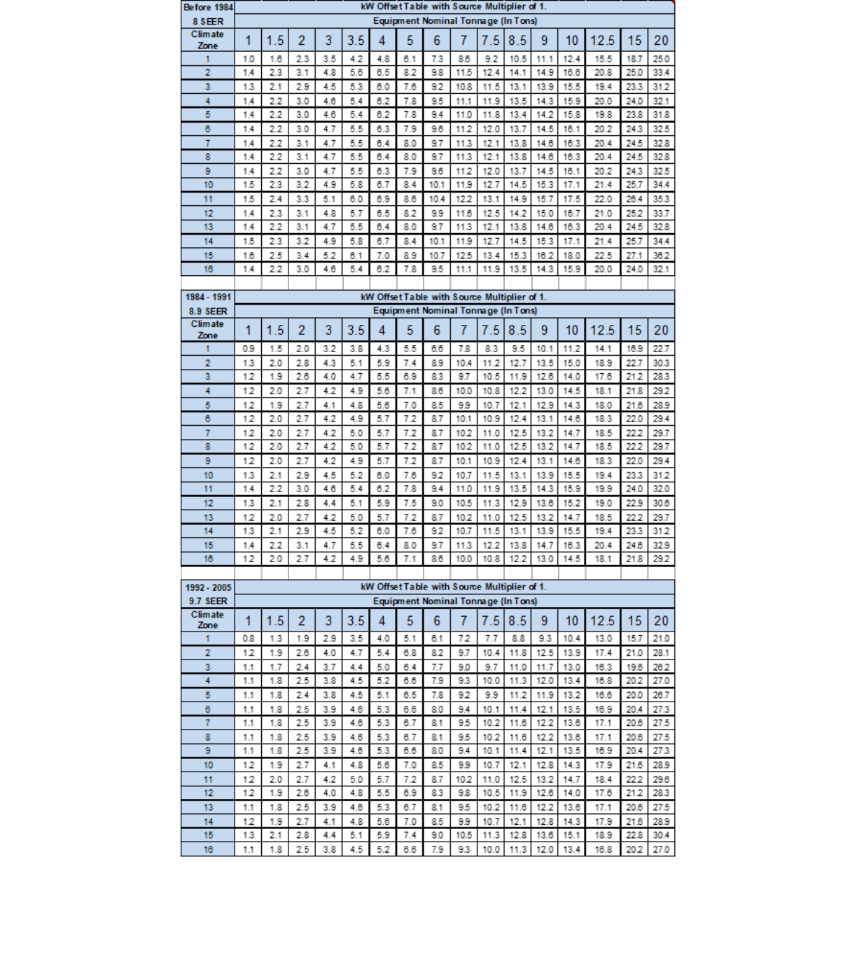
123
Appendix C – Conversion Tables for HVAC-Integrated S-TES
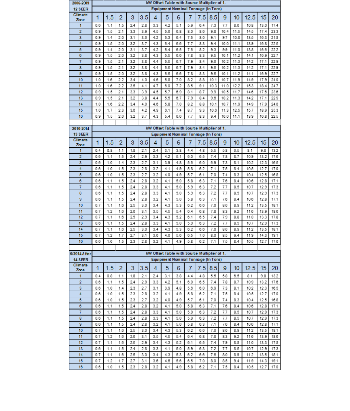
124

125
Appendix D – Calculation of Minimum Roundtrip Efficiency
Table 1: Minimum Roundtrip Efficiency Calculation
Line Loss On Peak
10.3%
Line Loss Off Peak
5.3%
Degradation Rate
1.0%
First-Year RTE
69.6%
Ten-Year Avg RTE
66.5%
Sum of Ann’l GHGs
0
Table 2: GHGs Over a 10-Year Period
Year
Off-Peak ER
On-Peak ER
GHG Emitted
GHG Avoided
Net GHG per MWh
1
382
544
580
606
-27
2
382
544
585
606
-21
3
382
544
591
606
-15
4
382
544
597
606
-9
5
382
544
603
606
-3
6
368
524
587
584
3
7
368
524
593
584
9
8
368
524
599
584
15
9
368
524
605
584
21
10
368
524
611
584
27

126
Appendix E – Incentive Rate for Large-Scale Storage Projects
Claiming the ITC at All Incentive Levels
Table 1: Large-Scale Storage Budget Incentive Rates with and without ITC
$/Wh
$/Wh
$/Wh
$/Wh
$/Wh
$/Wh
$/Wh
$/Wh
$/Wh
Non-ITC
0.50
0.45
0.40
0.35
0.30
0.25
0.20
0.15
0.10
ITC
0.36
0.32
0.29
0.25
0.22
0.18
0.14
0.11
0.07

127
Appendix F – Large Thermal Energy Storage UC Davis
Methodology for Determining 1-in-10 Year Peak
Large TES Calculation Methodology
1. Existing Air-Cooled Equipment
a. Developing Baseline
i. General
1. Measurements are taken during 2 separate periods
2. With ambient temperatures 85°F or greater
3. With greater than 4°F differential between measurement points
ii. IPLV elimination
1. Track supply air temperature leaving the unit (Direct expansion) or Chilled
Water Leaving Temperature (Chiller)
2. Progressively increase outside air fraction until supply temperature begins to
rise
b. Measurement
i. Measure true power at the point where temperature begins to rise
ii. If 100% outside air is incapable of producing a rise in supply temperature, additional
supplementary heat can be added to the ventilation air intake or return air system
c. Calculation
i. Establish the 1-in-10-year dry bulb temperature from the applicable ASHRAE
temperature file for the nearest weather station
ii. Derive the ratio between temperature change and power change from the power
measurements taken in terms of KW increase per 1°F
iii. Calculate the difference between the ASHRAE 10-year high temperature and the
highest temperature measured
iv. Using the highest measured temperature and the temperature/power change ratio
described above, calculate the KW of the system at ASHRAE 1-in-10 ambient air
temperature
2. Existing Water-Cooled Equipment
a. Developing Baseline
i. General
1. Measurements are taken during 2 separate periods
2. With ambient temperatures 85°F or greater
3. With greater than 4°F differential between measurement points
ii. Cooling Tower Manufacturer to provide expected condensing water temperature
given

128
1. Using the chiller manufacturer’s data for heat load rejected and
2. ASHRAE Dry Bulb and Wet bulb data for 1-in-10 conditions
iii. IPLV elimination
1. Cooling tower
a. Raise condenser water inlet temperature to the chiller to anticipated
1-in-10 temperature by controlling cooling tower air flow
b. Maintain full mass flow of condenser water
2. Track Chilled Water Leaving Temperature
3. Progressively increase outside air fraction until supply temperature begins to
rise
b. Measurement
i. Measure true power at the point where temperature begins to rise
ii. If 100% outside air is incapable of producing a rise in supply temperature, additional
supplementary heat can be added to the ventilation air intake or return air system
c. Calculation
i. Establish the 1-in-10-year dry bulb temperature from the applicable ASHRAE
temperature file for the nearest weather station
ii. Derive the ratio between temperature change and power change from the power
measurements taken in terms of KW increase per 1°F
iii. Calculate the difference between the ASHRAE 10-year high temperature and the
highest temperature measured
iv. Using the highest measured temperature and the temperature/power change ratio
described above, calculate the KW of the system at ASHRAE 1-in-10 ambient air
temperature
3. New Equipment
a. Applicant to submit a declaration of the schedule of equipment that would have been used if
the program did not exist
i. Manufacturers attesting to this performance must declare that the values calculated
at the given temperatures are interpolated values from physically tested values
measured in tests in a controlled environment
b. From have manufacturer’s provide data on equipment KW at ASHRAE 1-in-10 ambient heat
values for
i. Default equipment
ii. Proposed equipment
c. The difference between the 2 equipment schedules is the peak KW differential

129
Appendix G – Large Thermal Energy Storage Upfront and PBI
Incentive Calculation Methodology
Estimating the kW Offset
1. Model building as per former PLS program
2. Analyze model data as follows:
a. Existing system
i. Divided into 1°F bins based upon ambient DB temperature,
ii. Further divided into separate occupied and unoccupied bins
b. Proposed system
i. Model KW of Proposed System Configurations
1. TES System off (8760)
2. TES System recharging (8760)
3. TES System discharging (8760)
ii. Divide each Configuration into 1°F bins for each occupancy type
1. Occupied
2. Unoccupied
3. Bin to represent 1 hour of time
iii. Interpolation
1. Extend bins
a. From highest modeled temperature (TMY3 worst hour)
b. To 1-in-10 worst hour
2. Number of bins
a. One bin for 1-in-10 worst hour
b. Two bins for next lower temperature
c. Continue this extension, with number of bins never less than two nor
higher than the number of hours at highest DB in TMY3 file
3. Straight line estimate
a. Delta KW between
i. 1-in-10 high KW
ii. Highest hour
b. Divided by number of °F between 1-in-10 and TMY3
c. Applied equally to each bin between high and low
Pre & Post Monitoring Parameters for PBI Calculations
3. Pre-Monitoring
a. Monitor total KW of all affected HVAC equipment

130
i. Water cooled chiller
1. Chiller
2. Condenser water pumps
3. Cooling tower fans/Pumps
4. Chilled water pumps
ii. Air cooled Chiller
1. Chiller
2. Chilled water pumps (if separate)
iii. Air Cooled DX units (if replaced with Chilled water)
1. All units being upgraded
b. Ambient DB Air temp
i. From nearest National Weather Service recognized weather station
c. Monitoring location
i. Typically, at unit
ii. Where one sub panel serves HVAC equipment exclusively, can be monitored at that
panel
iii. Monitoring plan to show where metering is located
d. Data requirements
i. Peak KW as described in UC Davis methodology
ii. kWh
1. Hourly Bins
a. By occupied/unoccupied
b. Per 1°F
c. Average for hour
i. Temp
ii. KW
2. Data collection
a. Collected every 4 seconds
b. Stored locally
c. Averaged
d. Reported/recorded as a “Block” by PDP every five minutes
3. Data Required for each “Block”
a. Time stamp
b. Ambient air temp
c. KW of all HVAC equipment to be impacted by installation
d. CPUC GHG signal (once available)
4. Minimum 240 reported Blocks @ >90°F

131
e. Pre-monitoring reporting
i. KW monitoring points to be reported to PA in advance
ii. PA to approve or reject monitoring points plan w/in 10 business days of submission
iii. Applicant to inform PA when monitoring equipment is in place
f. Model kWh Calibration
i. Collected KW data averaged per bin
ii. Model data averaged per bin
iii. If model average KW per bin is over/under by >10% for any individual bin, or >5% for
any four consecutive 1°F bins, model to be calibrated to match measured data
g. Data set editing
i. Where the number of hours in the TMY3 file for a given °F are less than half of the
two adjacent hours, the following method shall be used
1. Average the number of hours for the next higher and lower ambient air temps
to derive the adjusted number of slots for that bin
2. Average the mean KW for the next higher and lower ambient air temps to
derive the adjusted KW for that bin
Large TES systems also have post installation monitoring and reporting requirements during the PBI
period.
These are described in the section below:
4. Post Monitoring
a. Duration: five years from start-up
b. Monitored points
i. Baseline points remain the same
1. KW of HVAC equipment
2. Ambient DB air temp
3. Occupied/unoccupied
ii. Additional TES operation related bins added
1. TES Discharge
2. TES Recharge
c. Monitoring frequency remains same
d. Analysis of kWH
i. Full Discharge hours
1. A full discharge hour is any hour where the TES system is in operation for all
60 minutes
2. All 12 report Blocks are averaged for
a. KW

132
b. Ambient air temp in °F
3. Average KW for this hour is compared to the average KW of the current
baseline system for that temperature and status combination
4. The difference between the Average hourly KW of the baseline system and
the average hourly KW of the TES system in discharge mode will be the
attributable kWh for that hour
ii. Partial discharge hours
1. In cases where the TES system is not discharged starting at the top of a
given hour, the following pro-rated process is used
2. Five-minute report Blocks are collected for the entire hour
3. Only five-minute report Blocks collected when the TES system is in
discharge are considered
4. For any five-minute report that is divided between discharge / recharge /
normal operation states, the state with the most 4 second measurements
shall be the reported state, with KW averaged across those all
measurements of that state for the reporting period
5. The difference between the Average hourly KW of the baseline system and
the average hourly KW of the TES system for all reports in discharge mode
times the fraction of the hour the system was in discharge mode will be the
attributable kWh for that hour.
e. Current baseline updating
i. The initial baseline will be populated from the calibrated pre-monitoring baseline as
mentioned above
ii. Each individual temperature/status bin will have the number of hour “slots” that it had
in the initial 8760 TMY3 based model + any “extension” hours added to get to the 1-
in-10 temperature
iii. As actual post installation data is acquired, it displaces the original modeled data.
iv. The process is continuous over life of project, so that the non-discharge baseline is
continuously reset with actual data
v. Actual Baseline updating occurs after the end each month to set the updated
baseline for the next month
f. Original baseline retention and use
i. The original calibrated baseline is retained.
ii. The original baseline is NOT used for calculating Performance Based Incentives
iii. The original baseline is retained and used for calculating the GHG impacts of the
installation Example 1: There are 48 hours at 97°F for a given location in a given
TMY3 file. The number of “slots” in the occupied/97°F bin is fixed at 48. In Year 1

133
there are 55 hours at 97°, and in Year 2 there are 39 hours at this temperature. As
each new “measured” hour is added to the database it pushes an originally modeled
hour out. In such a case, all the modeled data would all be pushed out of this bin
before the end of Year 1, while by the end of Year 2 the slots in that bin would be
almost all from Year 2.
5. Reporting
a. Monthly reports in PDF and data to be provided in Excel or CSV format
b. Data Summary
i. Location
ii. Project identifying information
iii. Discharge kWh shifted
1. Used for PBI purposes
2. kWh
a. Sum of measured kWh of all Discharge blocks in month
b. Less sum of mean kWh of all block of same temp/status bin from
current baseline
c. Difference is net monthly Discharge kWh
iv. Net GHG impact/kWh
v. GHG signal
1. Recharge GHG
a. Sum of measured kWh of all Recharge blocks in month x five-minute
GHG signal
b. Less sum of mean kWh of all block of same temp/status bin from
current baseline x five-minute GHG signal
c. Difference is net monthly Recharge GHG
2. Discharge GHG
a. Sum of kWh of all Discharge blocks in month of same temp/status
bin from original calibrated baseline x five-minute GHG signal.
b. Less sum of measured kWh of all Discharge blocks
c. Difference is net monthly Discharge GHG
3. Discharge GHG (saved) less Recharge GHG = Net total GHG impact
4. Net total GHG impact / sum of Discharge kWh = Net total GHG/ kWh for the
month.
c. Detailed data
i. All five-minute Blocks for month, including:
1. Time stamp
2. Discharge/Recharge/Normal operation status

134
3. Ambient air DB temperature
4. Occupied/unoccupied
5. Five-Minute GHG Signal (once available)
ii. Current Baseline
1. Current Baseline for this month (from last monthly update)
2. Updated Current Baseline
a. For next month
b. incorporating the insertion of the reporting month’s data into the
baseline database
c. displacing older data from the database
Data rolled up from the meter interval report into the app interval report must follow the format specified
by the SGIP database manager in the latest file format spec.

135
Appendix H – Incentive Calculation Examples
Energy Storage Incentive Duration Decrease Examples
Table 1: Energy Storage Incentive Duration Decrease (Projects with backup capability) Calculation
Example 1: Four-hour system at $.40/Wh incentive rate with a discharge rating of 100 kW
and a discharge capacity of 400 kWh (400,000 Wh)
Given
Calculation
Discharge Rating:
100,000 W
Total Duration: 4
hours
Total Discharge
Capacity: 400,000
Wh
Incentive Rate:
$0.40/Wh
Step 1
Calculate incentive for the first 2-hr discharge duration (0-2hrs) in a 4-hr
system:
100,000 W × 2h × $0.40/Wh × 100% = $80,000
Step 2
Calculate incentive for the second 2-hr discharge duration (2-4hrs) in a 4-hr
system:
100,000 W × 2h × $0.40/Wh × 100% = $80,000
Step 3
Calculate total incentive:
$80,000 + $80,000 = $160,000
Table 2: Energy Storage Incentive Duration Decrease (Projects with backup capability) Calculation
Example 2: Six-hour system at $.40/Wh incentive rate with a discharge rating of 100 kW and
a discharge capacity of 600 kWh (600,000 Wh)
Given
Calculation
Discharge Rating:
100,000 W
Total Duration: 6
hours
Total Discharge
Capacity: 600,000
Wh
Incentive Rate:
$0.40/Wh
Step 1
Calculate incentive for the first 2-hr discharge duration (0-2hrs) in a 6-hr
system:
100,000 W × 2h × $0.40/Wh × 100% = $80,000
Step 2
Calculate incentive for the second 2-hr discharge duration (2-4hrs) in a 6-hr
system:
100,000 W × 2h × $0.40/Wh × 100% = $80,000
Step 3
Calculate incentive for the third 2-hr discharge duration (4-6hrs) in a 6-hr
system:
100,000 W × 2h × $0.40/Wh × 50% = $40,000
Step 4
Calculate total incentive:
$80,000 + $80,000 + $40,000 = $200,000

136
Table 3: Energy Storage Incentive Duration Decrease (Projects without backup capability) Calculation
Example 1: Four-hour system at $.40/Wh incentive rate with a discharge rating of 100 kW
and a discharge capacity of 400 kWh (400,000 Wh)
Given
Calculation
Discharge Rating:
100,000 W
Total Duration: 4
hours
Total Discharge
Capacity: 400,000
Wh
Incentive Rate:
$0.40/Wh
Step 1
Calculate incentive for the first 2-hr discharge duration (0-2hrs) in a 4-hr
system:
100,000 W × 2h × $0.40/Wh × 100% = $80,000
Step 2
Calculate incentive for the second 2-hr discharge duration (2-4hrs) in a 4-hr
system:
100,000 W × 2h × $0.40/Wh × 50% = $40,000
Step 3
Calculate total incentive:
$80,000 + $40,000 = $120,000
Table 4: Energy Storage Incentive Duration Decrease (Projects without backup capability) Calculation
Example 2: Six-hour system at $.40/Wh incentive rate with a discharge rating of 100 kW and
a discharge capacity of 600 kWh (600,000 Wh)
Given
Calculation
Discharge Rating:
100,000 W
Total Duration: 6
hours
Total Discharge
Capacity: 600,000
Wh
Incentive Rate:
$0.40/Wh
Step 1
Calculate incentive for the first 2-hr discharge duration (0-2hrs) in a 6-hr
system:
100,000 W × 2h × $0.40/Wh × 100% = $80,000
Step 2
Calculate incentive for the second 2-hr discharge duration (2-4hrs) in a 6-hr
system:
100,000 W × 2h × $0.40/Wh × 50% = $40,000
Step 3
Calculate incentive for the third 2-hr discharge duration (4-6hrs) in a 6-hr
system:
100,000 W × 2h × $0.40/Wh × 25% = $20,000
Step 4
Calculate total incentive:
$80,000 + $40,000 + $20,000 = $140,000

137
Table 5: Energy Storage Performance-Based Incentive (PBI) Payment Calculation Example
Example PBI Payment for a Two-Hour System: 100 kWh system at $.50/Wh
Description
Calculation
Result
Total incentive
= 100,000 Wh * $.50/Wh
$50,000
Upfront payment
= $50,000 * 50%
$25,000
Remaining payment to be
recuperated through PBI
= $50,000 * 50%
$25,000
Total anticipated kWh
discharged/offset
= 100 kWh * 104 full discharges * 5 years
52,000 kWh
$/kWh for anticipated kWh
discharged/offset
= $25,000 / 52,000 kWh
$0.480769230/kWh
$/kWh for anticipated kWh
discharged/offset
= 100 kWh * 104 full discharges * $0.
480769230/kWh
$5,000
California Manufacturer Total Value of Capital Equipment Calculation Examples
Example 1
An energy storage project requests the California Manufacturer
99
incentive adder. The project provides
the following cost breakdown:
Table 6: California Manufacturer Total Value of Capital Equipment Calculation Examples
Equipment Type
Manufacturer
Cost
Location
Manufactured
Approved CA
Manufacturer
Energy Storage
Medium
ABC Company
$12,000
Los Angeles, CA
Yes
Inverter
Lizard Inverters
$3,000
San Diego, CA
Yes
Balance of System
Nick Controllers
$2,000
South Korea
No
• Total system cost = $17,000
• Cost percentage of equipment components manufactured in California = 88%
Result: The project is eligible to receive the California Manufacturer Adder.
99
The manufacturer must be the entity responsible for the assembly and manufacturing of a substantial portion of the assembly of
the final product, as described in Section 4.4.1.

138
Example 2
An energy storage project requests incentive adder. The project provides the following cost breakdown:
Table 7: California Manufacturer Total Value of Capital Equipment Calculation Examples
Equipment Type
Manufacturer
Cost
Manufacturing
Location
Approved CA
Manufacturer?
Energy Storage
Medium
XYZ Company
$16,000
Philadelphia, PA
No
Inverter
Lizard Inverters
Company
$3,000
San Diego, CA
Yes
Balance of System
Golden Gate
System Company
$11,000
San Francisco, CA
Yes
• Total system cost = $30,000
• Cost Percentage of equipment components manufactured in California = 46.7%
Result: The project is ineligible to receive the California Manufacturer Adder.
HVAC-integrated S-TES System Energy Capacity Calculation Examples
Example 1: Systems that fully avoid compressor(s) run-time during its entire discharge duration
Calculate the rated capacity of a HVAC-integrated S-TES system for a 5-ton HVAC unit with a 12 SEER
rating in Climate Zone 10. During the S-TES system’s discharge duration, the HVAC unit’s compressor is
entirely substituted for the full 180-minute duration.
1. Using the Conversion Table in Appendix C, the peak kW Offset is 5.8 kW.
2. Energy Capacity = 5.8 kW x 180 minutes x (1 hour / 60 minutes) = 17.4 kWh
Example 2: Systems with compressor(s) running a percentage of time during its discharge duration
Calculate the rated capacity of a HVAC-integrated S-TES system for a 5-ton HVAC unit with a 12 SEER
rating in Climate Zone 10. During the S-TES system’s discharge duration, the HVAC unit’s compressor is
running 60 minutes of the 180-minute duration with the maximum compressor operation being five
minutes in every 15-minute interval.
1. Using the Conversion Table in Appendix C, the peak kW Offset is 5.8 kW.
2. The compressor runtime during TES system’s discharge duration is 60 minutes (180 minutes x 5 / 15
minutes)
3. The minimum avoided compressor run-time is 120 minutes (180 minutes - 60 minutes)
4. Energy Capacity = 5.8 kW x 120 minutes x (1 hour / 60 minutes) = 11.6 kWh
HVAC-integrated S-TES System Rated Capacity Calculation Example
Example 1: Systems with compressor(s) running a percentage of time during its discharge duration

139
Calculate the rated capacity of a HVAC-integrated S-TES system for a 5-ton HVAC unit with a 12 SEER
rating in Climate Zone 10. During the S-TES system’s discharge duration, the HVAC unit’s compressor is
running 60 minutes of the 180-minute duration, where the maximum compressor operation is five minutes
in every 15-minute interval.
1. Using the Conversion Table in Appendix C, the peak kW Offset is 5.8 kW.
2. The compressor runtime during S-TES discharge duration is 60 minutes (180 minutes x 5 / 15
minutes)
3. The minimum avoided compressor run-time is 120 minutes (180 minutes - 60 minutes)
4. Rated Capacity = 5.8 kW x 120 minutes / 180 minutes = 3.87 kW
