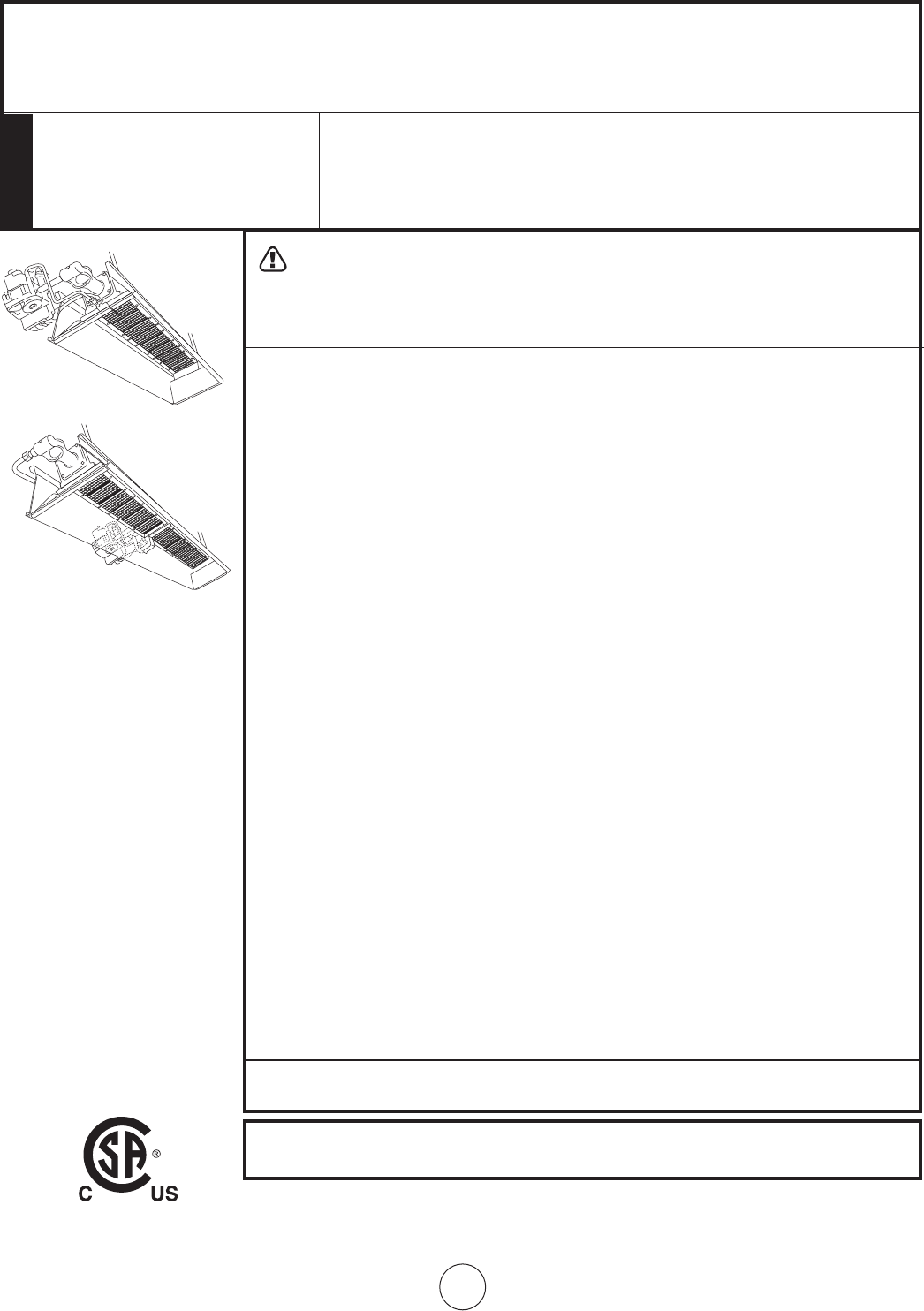
OPERATING INSTRUCTIONS AND OWNER’S MANUAL
READ INSTRUCTIONS CAREFULLY: Read and follow all
instructions. Place instructions in a safe place for future
reference. Do not allow anyone who has not read these
instructions to assemble, light, adjust or operate the heater.
HEATSTAR High-Intensity Infrared Heaters
LANGUAGES
MODELS
Installer: Leave this manual with the appliance. Consumer: Retain this manual for future reference.
If the information in this manual is not followed exactly, a fire or explosion
may result causing property damage, personal injury or loss of life.
WARNING:
— Donotstoreorusegasolineorotherflammablevaporsandliquidsinthevicinityofthisorany
other appliance.
— WHATTODOIFYOUSMELLGAS
• OpenWindows
• DO NOT try to light any appliance.
• DO NOT use electrical switches.
• DO NOTuseanytelephoneinyourhouse.Immediatelycallyourlocalgassupplierfroma
neighbor'stelephone.Followthegassupplier'sinstructions.
• DO NOT touch any electrical switch; do not use any phone in your building.
• Installationandservicemustbeperfomedbyaqualifiedinstaller,serviceagencyorthegas
supplier.
• Ifyoucannotreachyourgassupplier,calltheFireDepartment.
Thisisanunventedgas-firedheater.Itusesair(oxygen)fromtheareainwhichitisused.Adequate
combustionandventilationairmustbeprovided.Refertopage4&5
ENERCOGROUPINC.,4560W.160THST.,CLEVELAND,OHIO44135•866-447-2194
4000 & 8000 Models
9000 Models
HS4030 HS8070 HS9100
HS4040 HS9080 HS9120
HS8050 HS9090 HS9140
HS8060 HS9100S
E2
Enerco Group, Inc. |Gas-Fired Infra-Red Space Heaters Operating Instructions and Owner’s Manual
CONTENTS
GeneralInformation .......................................................... 3
Clearances ........................................................................ 3
GasSupply ........................................................................ 3
GasPressure ..................................................................... 4
Electrical ........................................................................... 5
Thermostat&Location ...................................................... 5
Ventilation ........................................................................ 5
Operations ........................................................................ 5
CleaningInformation ........................................................ 5
Thermostat ....................................................................... 6
Troubleshooting ................................................................ 7
Connection diagram for flame rod current
for flame rectification systems ...................................... 8
Replacement parts ............................................................ 9
Control system replacement parts ....................................12
WARNING: Improperinstallation,adjustment,
alteration,serviceormaintenancecancauseproperty
damage, injury or death. Read the installation,
operation, and maintenance instructions thoroughly
beforeinstallingorservicingthisequipment.For
assistanceoradditionalinformationconsultaqualified
installer,serviceagency,orgassupplier.
WARNING: Whenusedwithoutfreshair,heater
maygiveoffCARBONMONOXIDE,anodorless
poisonousgas.OPENWINDOWANINCHORTWO
FORFRESHAIRWHENUSINGHEATER.
WARNING: ThisheaterisequippedwithaPILOT
LIGHTSAFETYSYSTEM.DONOTTAMPERWITHPILOT
LIGHTSAFETYSYSTEM.
WARNING: Ifheatershutsoff,donotrelight
untilyouprovidefreshair.Ifheaterkeepsshuttingoff,
haveitserviced.Keepburnerandcontrolclean.Open
doorfor5minutes.
MaintainclearancesasshowninFigure1oronheaternameplate.
•DONOTUSEMATCHOROTHERFLAME
FORLEAKTESTING.
•DONOTEXCEED1/2PSIINLETPRESSURETOHEATER.
DANGER:
Carbonmonoxidepoisoningmayleadtodeath.
Carbon Monoxide Poisoning:
Earlysignsofcarbonmonoxidepoisoningresemble
theflu,withheadaches,dizziness,ornausea.Ifyou
havethesesigns,theheatermaynotbeworking
properly.Getfreshairatonce!Haveheaterserviced.
Somepeoplearemoreaffectedbycarbonmonoxide
thanothers.Theseincludepregnantwomen,persons
with heart or lung disease or anemia, those under the
influence of alcohol, and those at high altitudes.
CAUTION:
•Neverconnectgasvalveorthermostattolinevoltage
or a transformer.
•Iftheinfra-redcolorofthegridbecomesdullwhen
the building furnace is operating, consult gas supplier
on correct gas supply piping sizes.
•Thisheaterisforindoorinstallationonly!
NOTEGasketbindermaterialusedinthisheaterassem-
blywilltemporarilyemitanodorand/orvapor.This
conditionwillclearupinapproximately20minutes
andthereafterwillnotreoccur.Refertopage4for
ventilation.
THE STATE OF CALIFORNIA REQUIRES THE
FOLLOWING WARNING:
WARNING: Combustionby-productsproduced
whenusingthisproductcontaincarbonmonoxide,
achemicalknowntotheStateofCaliforniatocause
cancerandbirthdefects(orotherreproductiveharm).
LANGUAGES
ENGLISH
Pages E1 — E16
SPANISH
Pages S1 — S16
FRENCH
Pages F1 — F16
E3
Operating Instructions and Owner’s ManualEnerco Group, Inc. | Gas-Fired Infra-Red Space Heaters
1. GENERAL INFORMATION
a. Yourheatercomesfullyassembledandistestedat
the factory for proper gas and input as stated on
the name plate.
b. Beforeproceedingwiththeinstallation,besuretoin-
spectfordamages.Thefreightcompanythatdelivered
the heater must be notified of any damages prior to
installation.HEATSTARwillsendreplacementpartsfor
damagedpartsonlyafterreceivingasignedinspection
reporttoprovetheliabilityofthefreightcompany.
c. Do not attempt to operate heater with any other gas
than that indicated on the heater name plate.
d. Installationoftheheatermustconformwithlocal
building codes or, in absence of local codes, with
theNationalFuelGasCode,ANSIZ223.1/NFPA54.In
Canada,refertoCAN1-B146.1.
e. Plugged1/8”N.P.T.TestGageConnectionislocated
ontheHeaterGasControloraN.P.T.Connectionis
locatedontheoutsideoftheCastVenturi.
2. CLEARANCES Minimum clearances to combustibles.
(Refer to Figure 1)
Provideadequateclearancetocombustibles,Figure
1,betweencontrolendofheaterforservicing
andminimumontopandsidesforventilationand
combustion air supply.
Aminimumclearanceof8’abovefloorforpublic
garagesinaccordancewithANSI/NFPANo.88most
recenteditionorFigure1;whicheverislarger.In
CanadarefertoCAN1-B149.1Installationcodesfor
Gasburningappliances.
Aminimumclearanceof10’fromthebottomof
heater to top of wing, or engine enclosure, where
aircraftarehoused,and8’abovefloorinotherareas
ofthehangerinaccordancewithANSI/NFPANo.409
mostrecentedition,orFigure1;thelargerdimension
ofANSI/NFPANo.409orFigure1istobeused.In
CanadarefertoCCAB149-1-M91.
WARNING: MAINTAINCLEARANCESASSHOWN
INFIGURE1ORONHEATERNAMEPLATE,INGARAGE
INSTALLATIONSWHEREPARKEDVEHICLESARE
DIRECTLYBELOWTHEHEATER.
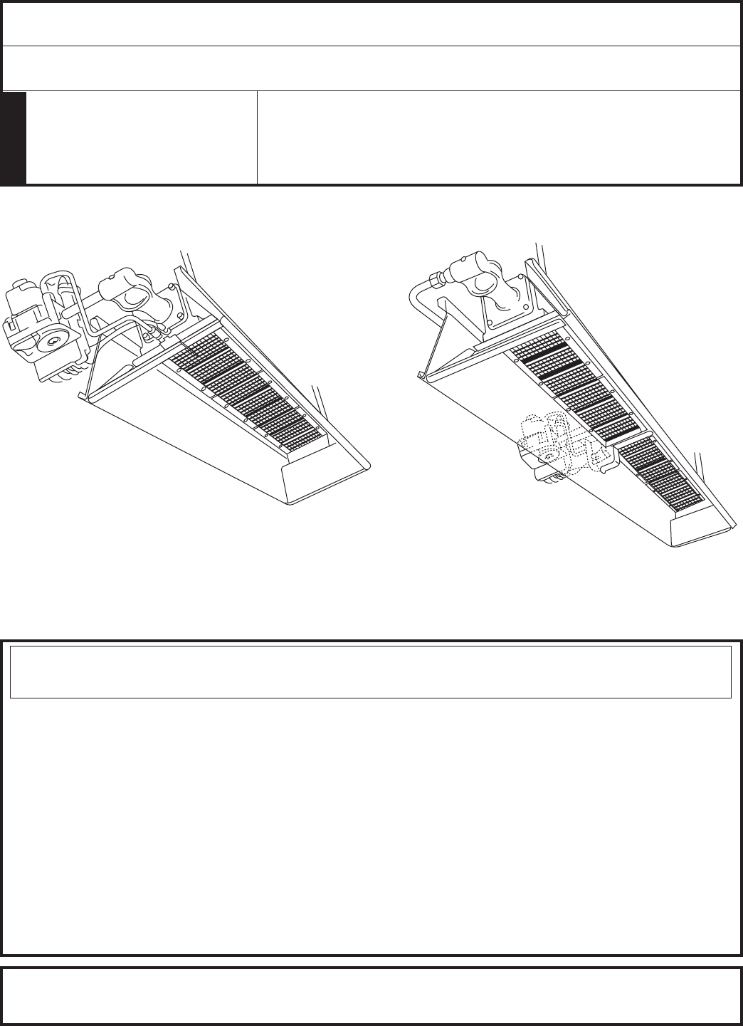
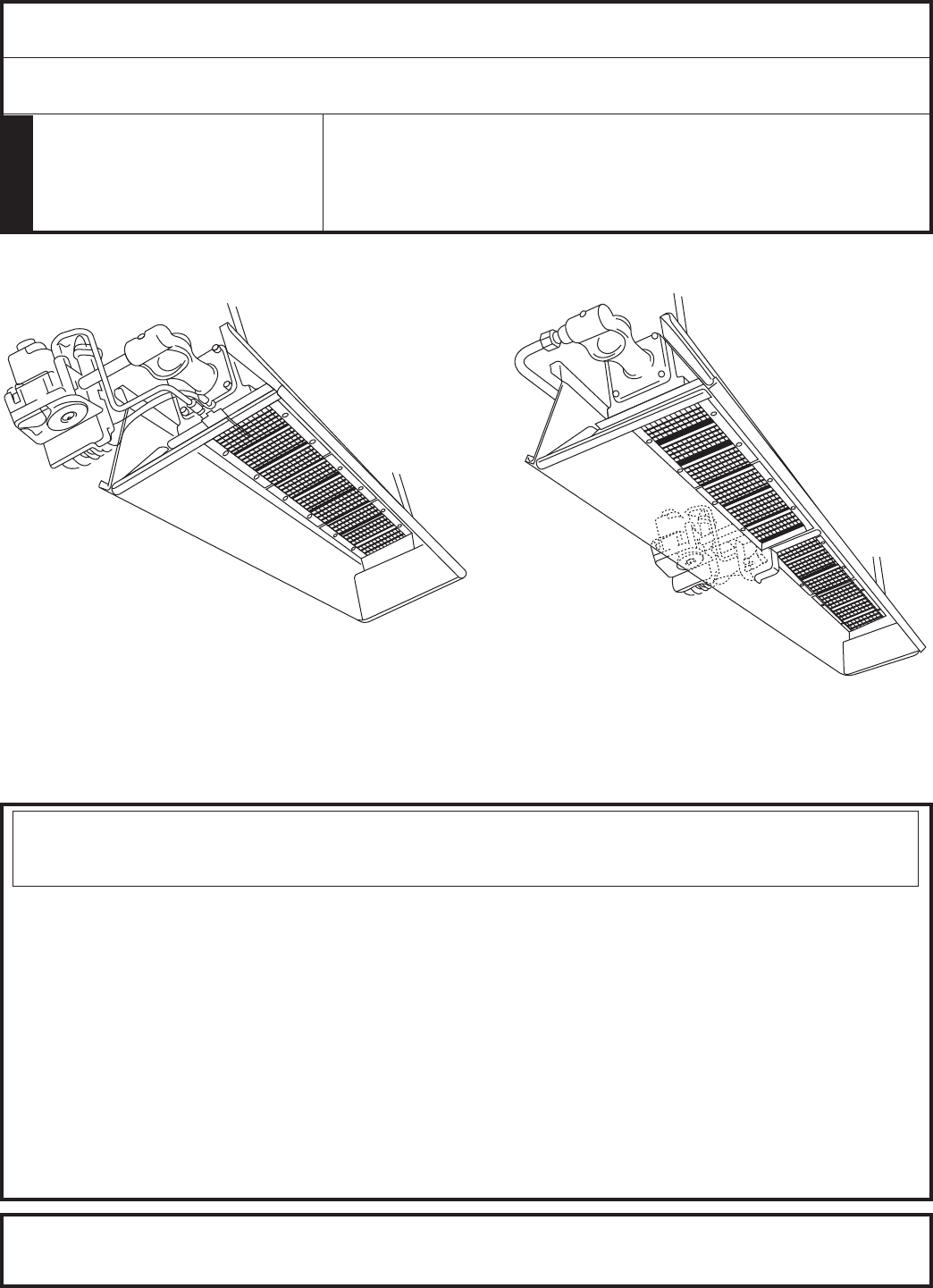
3. SUSPENSION
Heaterhasfourmountingholes,twooneachend,for
attachingrodorangleironbracketsandshallbesafely
andadequatelyfixedinpositionindependentofgas
andelectricsupplylines.RefertoFigures4,5,and7on
pages13and14forrecommendedsuspensions.
4. GAS SUPPLY
Provideadequategassupplyforratedinputofeach
heaterusingAmericanStandardInstallationofgas
pipingandgasappliancesinbuildingANSI/223.1a/
NFPA54Pamphlet,TableC-3showscapacityofpipe
of different diameters and lengths in cubic feet per
hourforNaturalGaswithpressuredropof0.3inches
specifygravityof0.60.ForliquefiedPetroleumGas
(LP)capacityrefertoTableC-3andC-15ofthesame
pamphlet.Forrecommendedheatergasconnection
refertoFigureNo.5,Page15.InCanadarefertoCAN
1-B149.1,andCSAB63.
Ifgaslinesaretobepressuretestedwithcompressed
air,disconnecteachheatertopreventcontroldamage
andcapoutlets.Afterreconnectingallheaters,purge
gaslinesofairandcheckallconnectionsforleaksus-
ing soap solution.
WARNING: DONOTUSEMATCHOROTHER
FLAMEFORLEAKTESTING.
5. PIPING REQUIREMENTS
Allpipinginstalledmustcomplywithlocalcodesandordinances
orwiththeNationalFuelGasCode,ANSIZ223.1(NFPA54),
whichevertakesprecedence.Wheninstallingpiping,thefollowing
requirementsmustbetakenintoconsideration:
• Usenewproperlyreamedblackpipefreefromchips.
• Applyagoodqualitypipecompoundtoallmalethreads
priortoassembly.IfL.P.gasisthefuel,ensurethatpipe
compoundisresistanttoL.P.gas.DONOTUSETEFLON
™ tape.
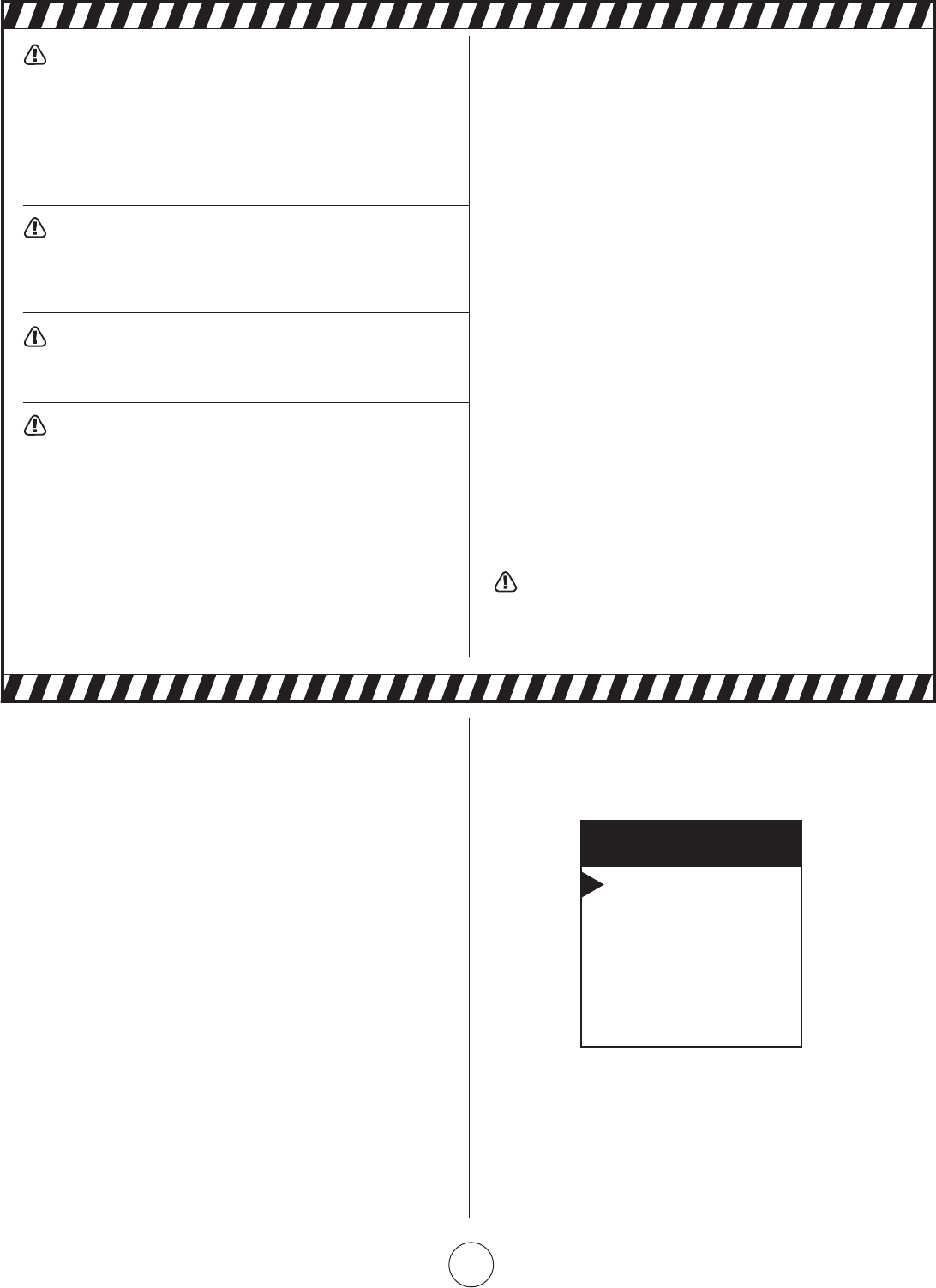
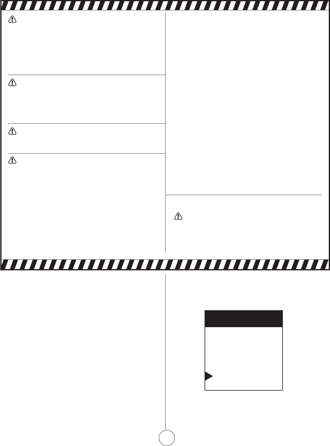
• Priortoinstallation,applypipecompoundtoallmale
threadsasshowninFigure1.
USE MODERATE AMOUNT OF PIPE DOPE
LEAVEFIRST2THREADSBARE
Figure 1. Pipe Compound Application
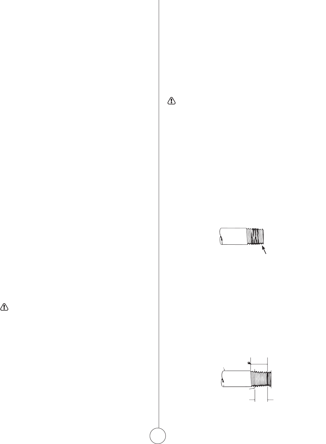
• Malethreadsonpipetobeinstalledintogasvalveshall
meettherequirementsofFigure2.Threadslongerthan
thoseshowninthefiguremaycausegasvalvedistortion
and malfunction.
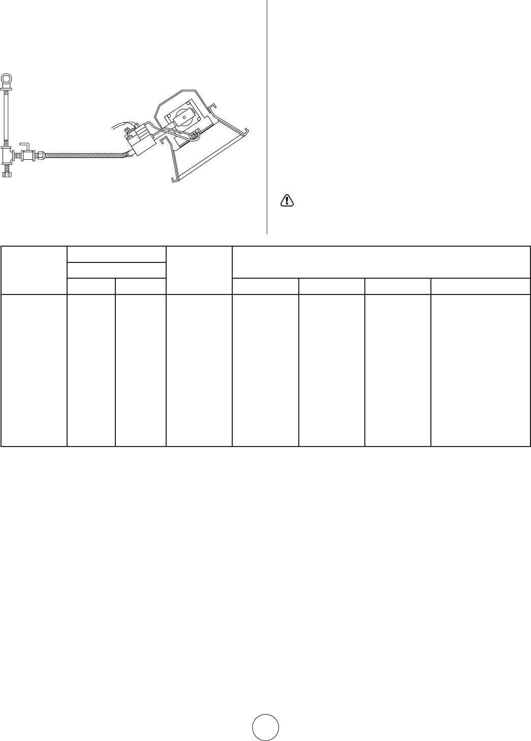
• Asedimenttrapmeetingthetypicalrequirementsof
Figure3shallbeinstalledinthelinetothegasvalve.
• Adedicatedshutoffvalvefortheheatermustbein-
stalled in the gas supply line.
¾”MAXIMUMTHREADLENGTH
½”BLACKPIPE
GASVALVEBODY
Figure 2.
Gas valve
connection
requirements
E4
Enerco Group, Inc. |Gas-Fired Infra-Red Space Heaters Operating Instructions and Owner’s Manual
NOTE:
1.OnlyUseAPipeCompoundWhichIsResistantToLiquefied
GasesOnL.P.Installations.
2.FittingsShownAreNotIncludedWithHeater.
Figure 3. Typical Piping Installation
Sediment trap
FIGURE 1
MODEL NO.
BTU/HR.RATING
NORMAL
MOUNTING
POSITION
CLEARANCESTOCOMBUSTIBLES
GAS
NATURAL PROPANE TOP SIDES BACK BELOW
4030** 30,000 30,000 Horiz.-45° 30” 30” 30” 54”
4040* 40,000 40,000 Horiz.-45° 34” 30” 30” 68”
8050** 50,000 50,000 Horiz.-45° 36” 30” 30” 78”
8060* 60,000 60,000 Horiz.-45° 40” 30” 30” 84”
8070** 70,000 – Horiz.-45° 40” 30” 30” 84”
9080** 80,000 80,000 Horiz.-45° 46” 40” 40” 104”
9090** 90,000 90,000 Horiz.-45° 46” 46” 46” 114 ”
9100S* 100,000 100,000 Horiz.-45° 48” 46” 46” 118 ”
9100** 100,000 100,000 Horiz.-45° 44” 40” 40” 104”
9120 * 120,000 120,000 Horiz.-45° 46” 46” 46” 114 ”
9140** 140,000 – Horiz.-45° 46” 46” 46” 114 ”
*HighIntensityHeatersareonlysoldas4040,8060,9100S,and9120
**Differentmodelnumbersareachievedbyusingsupplementalorificesincludedwithheaterstochangeheatoutput.
6. GAS PRESSURE
Whenahigherthanthemaximumrecommended
gas pressure is being maintained at the main gas line,
a separate regulator must be installed ahead of the
heater.RefertoFigure2formaximumallowablepres-
sure for stated model and gas.
See heater rating plate for minimum gas supply pres-
sure“ForthePurposeofInputAdjustment”
On a multiple heater installation it may be possible
touseonelargecapacityregulatororanindividual
regulatorforeachheater.Nevertheless,itis
recommendedpracticetomaketheentirepipesystem
aloop.Contactyourlocalrepresentativeorthefactory
for proper gas pressure reducing design stage.
WARNING: DONOTEXCEED½P.S.I.INLET
PRESSURETOHEATERSSHOWNINFIGURES1AND2
Theclearancestocombustiblesrepresentasurfacetemperatureof90°F(32°C)aboveroomtemperature.Buildingmaterialswithlowheat
tolerancemaybesubjecttodegradationatlowertemperatures.Itistheinstaller’sresponsibility.
E5
Operating Instructions and Owner’s ManualEnerco Group, Inc. | Gas-Fired Infra-Red Space Heaters
7. ELECTRICAL
Allexternalwiringmustbeinaccordancewiththe
existingelectricalcode.Usewiringdiagramfurnished
withheater.Besureelectricsupplycharacteristics
matchthosecalledforonthenameplate.Theunit
must be electrically grounded in accordance with the
NationalElectricalCode,ANSI/NFPA70,latestrevision.
InCanadarefertoCanadianelectricalcodeCSAC22.1
8. THERMOSTAT & LOCATION
Makesurethattheelectricalcharacteristicsofthe
thermostatmatchthoseoftheheatercontrols.Forbest
resultsthermostatshouldbepositioned5ft.above
floorwhereaircancirculatefreelyaroundit.DONOT
MOUNTdirectlytocold-sidewall,indirectdraftsor
directlybeneaththeinfra-redheater.
9. VENTILATION
a.Theminimumintakeandexhaustairopeningsshall
providefornotlessthan400CFMforevery100,000
BTUinputexceptthattheinfiltrationareamaybe
includedintheintakearea.Theexhaustfanmustbe
interlockedwiththeheaterthermostat.Ifapower
exhaustfanisused,itshouldbecontrolledbythe
thermostat or humidistat
b.Wherenatural(gravity)ventilationisprovidedfor
exhaust,theopeningsmustbedistributedabovethe
heaters(preferablyatthepeakoftheroof)andthe
areasofopeningsshallnotbelessthan300square
inchesforevery100,000BTUinput.
10. OPERATIONS
Uponcompletionofelectricalwiring,gaspipingand
purging of gas lines to heaters, refer to the lighting
instruction plate attached to heater for proper lighting
procedure.
11. CLEANING INFORMATION
BlowoutVenturiandburnerfacewithcompressedair
(25psimax.pressure);alsocleanorifices(seeFigure
2forcorrectsizedrill).Fordetailedmaintenanceand
cleaninginstructionscontactyourlocalrepresentative
or factory.
WARNING: GASKETBINDERMATERIALUSED
INTHISHEATERASSEMBLYWILLTEMPORARILY
EMITANODORAND/ORVAPOR.USEVENTILATION
(aORb)ANDTHISCONDITIONWILLCLEARUP
INAPPROXIMATELY20MINUTESANDWILLNOT
REOCCUR.
WARNING: DONOTATTEMPTTOIGNITE
THEPILOTBYHANDONHEATERSEQUIPPEDWITH
AUTOMATICSPARKIGNITION.
WARNING: THESTATEOFCALIFORNIAREQUIRES
THEFOLLOWINGWARNING:COMBUSTIONBY-
PRODUCTSPRODUCEDWHENUSINGTHISPRODUCT
CONTAINCARBONMONOXIDE,ACHEMICALKNOWN
TOTHESTATEOFCALIFORNIATOCAUSECANCER
ANDBIRTHDEFECTS(OROTHERREPRODUCTIVE
HARM).
NOTE: USELATESTEDITIONFORALLANSI
STANDARDANDCANADIANSTANDARDS.
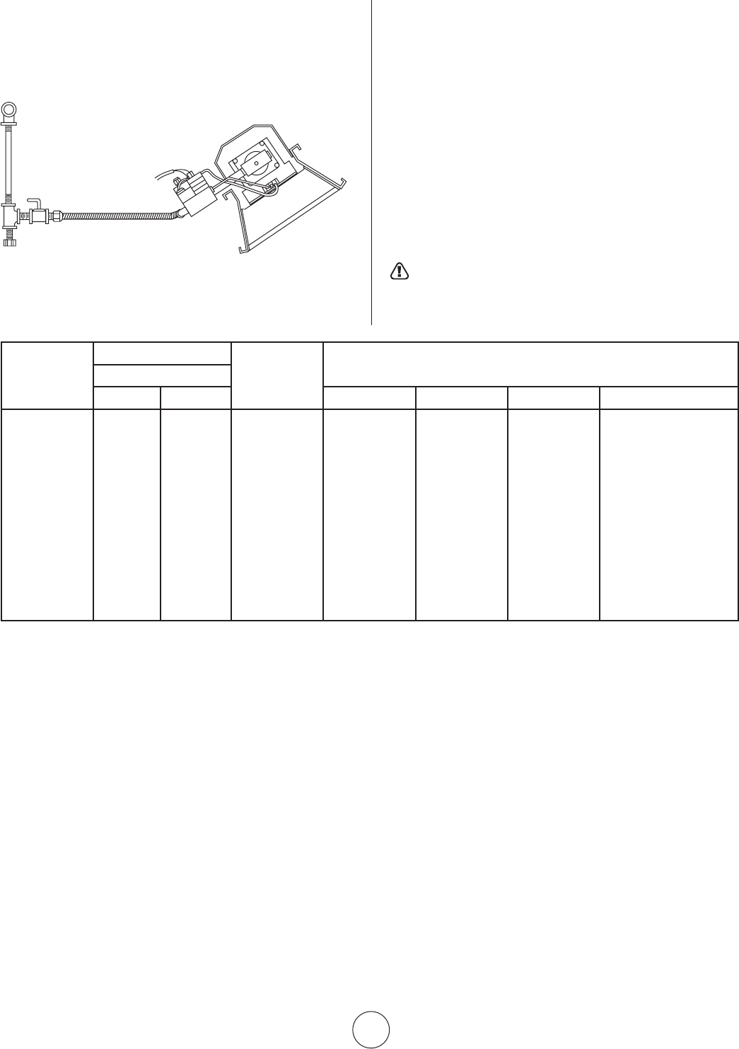
FIGURE 2
MODEL
NO.
BTU/HR.RATING GASSUPPLYPRESSURE(W.C.)
ORIFICESIZE
GAS MIN. MAX. MANIFOLD
NATURAL PROPANE NAT. L.P. NAT. L.P. NAT. L.P. NAT. L.P.
4030 30,000 30,000 6.6” 11 ” 14” 14” 5.6” 10” 43 52
4040 40,000 40,000 6.8” 11 ” 14” 14” 5.8” 10” 37 49
8050 50,000 50,000 7.0” 11 ” 14” 14” 4.3” 10” 30 45
8060 60,000 60,000 7.0” 11 ” 14” 14” 5.8” 10” 29 43
8070 70,000 – 7.0” – 14” – 6.0” – 28 –
9080 80,000 80,000 7.0” 11 ” 14” 14” 5.8” 10” 37 49
9090 90,000 90,000 7.0” 11 ” 14” 14” 5.0” 10” 32 47
9100S 100,000 100,000 7.0” 11 ” 14 ” 14 ” 5.0” 10” 31 46
9100 100,000 100,000 7.0” 11 ” 14” 14” 4.3” 10” 30 45
9120 120,000 120,000 7.0” 11 ” 14” 14” 5.8” 10” 29 43
9140 140,000 – 7.0” – 14 ” – 5.5” – 28 –
E6
Enerco Group, Inc. |Gas-Fired Infra-Red Space Heaters Operating Instructions and Owner’s Manual
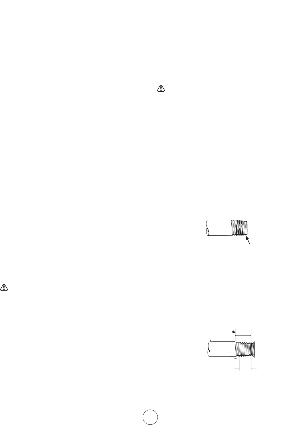
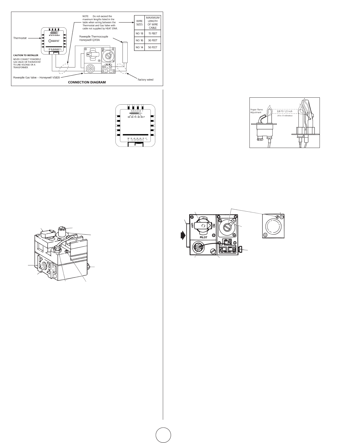
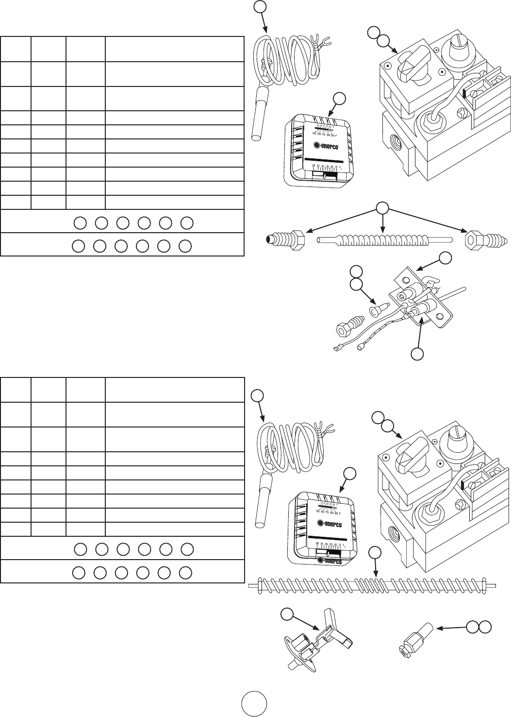
Figure 5.
Thermostat
controls
14. OPERATOR MAINTENANCE
INSTRUCTIONS
1. TROUBLESHOOTING
a.Table4listssystemissueswhichmayoccurduringthe
operation or maintenance of your heater.
b.ForadditionalinformationrefertoHoneywellField
Bulletinenclosedintheheatercarton.
c.Intheevent,resultscannotbeobtainedafterperform-
ingalllistedsolutions,callyourMr.Heaterdealer,orthe
factorycustomerservicedepartmentat1-866-447-2194.
2. ADJUSTING THE PILOT FLAME
Thepilotflameshouldenvelope
3/8to½in.(10to13mm)ofthe
tip of the thermocouple or
generator.Toadjustthepilot
flame:
12. START-UP PROCEDURE
MANUALGAS
CONTROLKNOB
WRENCH
BOSS
GASINLET
PRESSUREREGULATOR
ADJUSTMENT
STANDARD
PRESSURE
REGULATOR
(Incoming pressure
not exceed 13” W.C.)
PILOTGAS
OUTLET
(PRESSURE
TAPPING
DIRECTLY
BENEATH)
PILOTFLOW
ADJUSTING
SCREW
(BENEATH
COVERSCREW)
PILOTSTATPOWER
UNIT
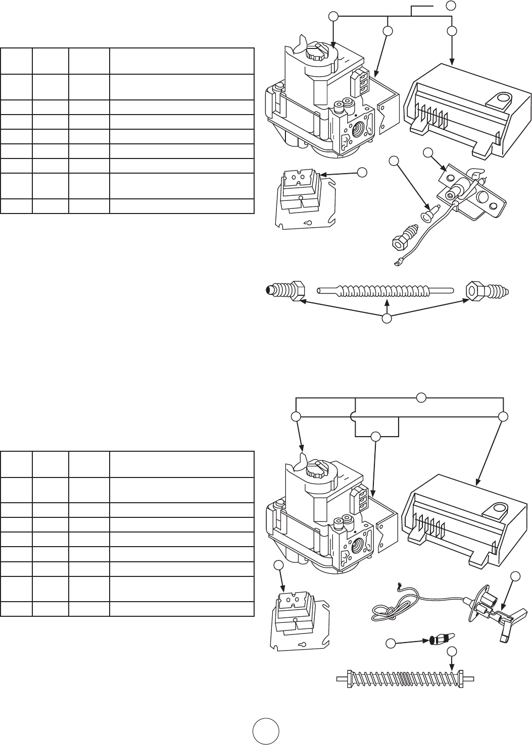
Figure 6. Gas Valve
Components
OPENTHEGASSUPPLYVALVEORVALVES.
SetthethermostattotheOFFposition.See
Figure5.Ifthemanualgascontrolknob
onthegasvalveisnotintheOFFposition,
partiallydepresstheknobandrotatetothe
OFFposition.SeeFigure6.
Wait5minutestoallowgasthatmayhave
accumulated in the main burner to escape
(especiallyimportantafterinstallation).
TurnthemanualgascontrolknobtothePILOTposition.
Depressthemanualgascontrolknob.Usingamatch,lightthe
pilotlight.SeeFigure6.Holdtheknobdownforapproximately
30secondstoallowanyairingaslinestopassthroughpilotand,
once the pilot is lit, allow the thermocouple to heat up enough to
activatethesafetyvalveinanopenposition.
ReleasemanualgascontrolknobandturntoON.Reset
thermostat to desired temperature.
NOTE:
DuringtheinitialstartupofMR.HEATERanodorand,perhaps,
somevaporwillcomefromtheheater.Thisisthegasketbinding
materialemittingthisodorand/orvapor.Afterapproximately20
minutes this odor will disappear and not occur again.
13. SHUTDOWN
1. TurnthermostattoOFF.
2. TurnmanualgascontrolknobongasvalvetoPILOT
position.
3. PartiallydepressknobandrotatetotheOFFposition.
4. Closegassupplyvalves.
a.Removepilotadjustment
coverscrew.RefertoFigure8.
b.Turninneradjustmentscrewclockwise
todecreaseorcounterclockwiseto
increase pilot flame.
c.Alwaysreplacecoverscrewafteradjustmentandtighten
firmly to ensure proper operation.
Manual gas
controlknob
Wrench
boss
Gas
inlet
Pilotstat
power unit
Pressure regulator
adjustment(beneath
coverscrew)
Installlong
screw in
outside corner
Standard
pressure
regulator
(“A”model)
Step
opening
regulator
(“C”model)
Pilot gas
outlet
(pressure
tapping
directly
beneath)
Pilot flow adjusting screw
(beneathcoverscrew)
Figure 8.
Top view
of standard
capacity gas
control.
13. REPLACING THE GAS VALVE UNIT
a.Removethetwogasvalveunitwiresatthegascontrol
valvelabeled“PP.”
b.Unscrewgasvalvefromgaspiping.
c.Reconnectgasvalveandunitwirestoterminals“PP.”Be
suretoleavethermostatwireononeterminal.
15. FREQUENCY OF OPERATOR CHECKS
Intermittent Use
Appliancesthatareusedseasonallyshouldbecheckedbefore
shutdownandagainbeforethenextuse.
Dusty,wetorcorrosiveenvironment.Sincetheseenvironmentscan
cause the gas control to deteriorate more rapidly, the system should
becheckedmoreoften.
The gas control should be replaced if:
a.Itdoesnotperformproperlyoncheckoutor
troubleshooting.
b.Thegascontrolknobishardtoturnorpushdown,orit
failstopopbackupwhenreleased.
THERMOSTAT
E7
Operating Instructions and Owner’s ManualEnerco Group, Inc. | Gas-Fired Infra-Red Space Heaters
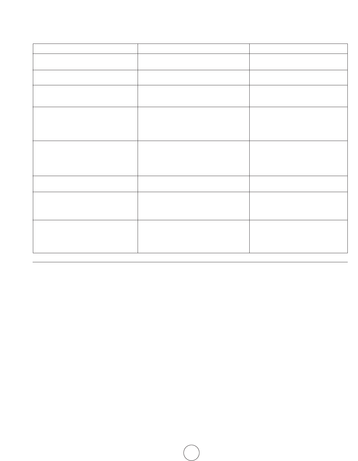
TABLE 4. TROUBLESHOOTING CHART
Belowinchartformarevarioussymptomsofamalfunctioning
system, possible defects that will cause there symptoms and
suggestedcorrectivemeasure.Thechartassumesthattheproper
gaspressureisavailabletotheheaterandthatthelighting
procedure is as stated on the plate attached to the heater.
SYMPTOMS CAUSES SOLUTIONS
Burnerlightoffveryslow Partiallyblockedpilotorifice Re-adjustpilot
Pilot out of adjustment Replace
Burnerlightoffveryslowly Partiallyblockedburnerorifice Replace
Color stays dull
Burnerflashback Lowgaspressure Correctlinepressureorcallyourgas
(roaringnoiseduringoperation supplier
andceramicgridsurfacewillbedark) Damagedburner Replace
Ceramic grid or burner sooting up
(whenneworaftercleaning) Firstcheckfordamaged Replaceifdamaged
burner orifice
Ifburnerorificeisnotdamaged
thencheckfordamagedmanifold. Replace
Pilotcannotbeignited Blockedpilotorifice Replace
Gascocknotinposition
Pilotgasflowadjustmentscrewmaybeclosed Gascontrolknobmustbeturnedtopilot
and held depressed
Openandadjust(seeFigure8)
Pilotlightsbutgoesout Defectivethermocouple Replace
Defectivecontrol Replace
Pilotstayslitbutmainburnerwillnotlight Loosewireorimproperlywired Tightenconnections,checkwiring
Defectivecontrol diagram
Blockedburnerorifice Replace
Clean orifice or replace
Failuretoignite Maingasoff Openmanualvalves
Airingasline Bleedgasline
Loosewireconnections Tightenwireconnections
Dirty wire connections Clean terminals and secure terminals
HIGH ALTITUDE OPERATION
1. PleasecontactthefactoryforadetailedHighAltitude
ConversionKittosuityourspecificneed.
1.1Bepreparedtoanswerfactoryquestions
regarding:Typeoffuelfortheproposedappliance
conversion,gaspressureavailableatsite,andspecific
altitude at site.
2. “Theconversionshallbecarriedoutbya
manufacturer’sauthorizedrepresentative,
inaccordancewiththerequirementsofthe
manufacturer,provincialorterritorialauthorities
havingjurisdictionandinaccordancewiththeir
requirements.”
3. HighAltitudeConversionKitswillincludehigh
altitude rating plate with stamped data, necessary
orificesorburnerasrequiredforspecificneedand
additional installation instructions.
4. InCanada,HeaterinstallationsatHighAltitudesshall
complywiththeapplicableconstructionprovisionsof
thecurrentstandardCAN1-2.17,gasfiredappliances
for use at high altitudes.
E8
Enerco Group, Inc. |Gas-Fired Infra-Red Space Heaters Operating Instructions and Owner’s Manual
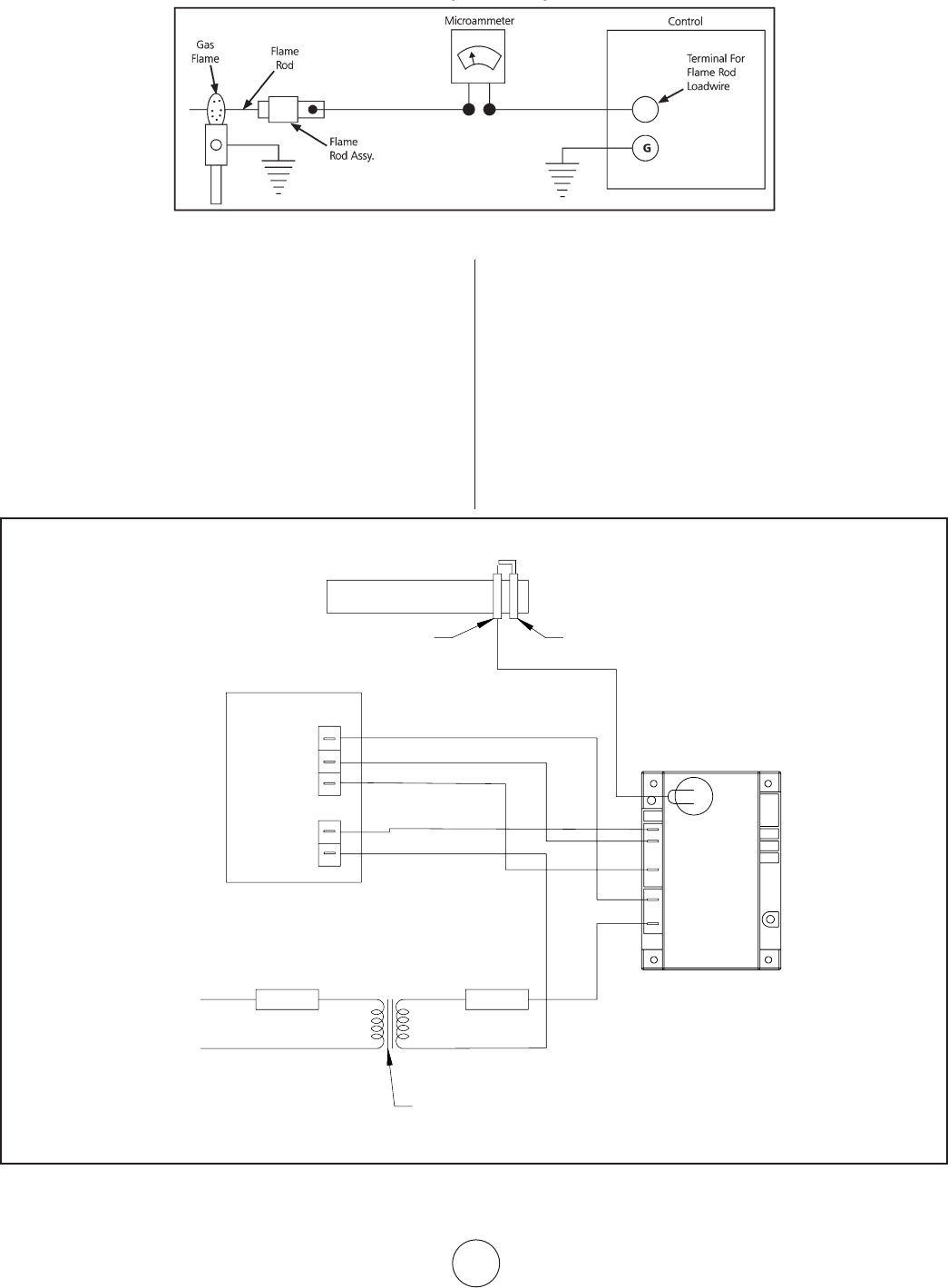
CONNECTION DIAGRAM FOR FLAME ROD CURRENT
FOR FLAME RECTIFICATION SYSTEMS (SP-MODELS)
MEANS OF PROVING ADEQUATE GROUNDING AREA
Theproperflame-rod-to-ground-arearatiocannot
alwaysbedeterminedbyvisualexaminationor
physicalmeasurement.Apositivemeansofchecking
the installation is the measurement of the flame rod
currentunderactualfiringconditions.Itisdefinitely
recommended that the installer measure the current
flow between the lead of the flame rod unit and the
terminalinthecontrolterminalboard(seeFigure3).
MeasurethecurrentwithaDCMicroammeterorequal.
Werecommendasteadyoutputof.9microamperes
ormore.Asteadyflowofcurrentinthisamountunder
actualfiringconditionswillgenerallyindicateadequate
grounding of the pilot flame.
NOTE:
1. Readallcontroldatasheetsuppliedwiththisheater.
2. Checkflamerodforanycontacttoheaterparts.Flame
rod must be free of any contact to heater. Contact with
heater will short circuit flame rod.
3. Crackedporcelainonflamerodwillshortcircuitsensor.
Replace flame rod.
Figure 3–Usingamicroammetertoproveadequategroundingarea.
GND
V2
FENWALL
IGNITION MODULE
IND/
MV1
V1/PV1
TH/W
SPARK
120VAC
24VAC
24 VOLT
THERMOSTAT
OPTIONAL
LINE VOLTAGE
THERMOSTAT
OPTIONAL
TRANSFORMER
(SHIPPED LOOSE)
GAS VALVE
PV
PV/MV
MV
VALVE
GROUND
MAIN BURNER
PILOT BURNER
SPARK ELECTRODE/FLAME SENSOR
E9
Operating Instructions and Owner’s ManualEnerco Group, Inc. | Gas-Fired Infra-Red Space Heaters
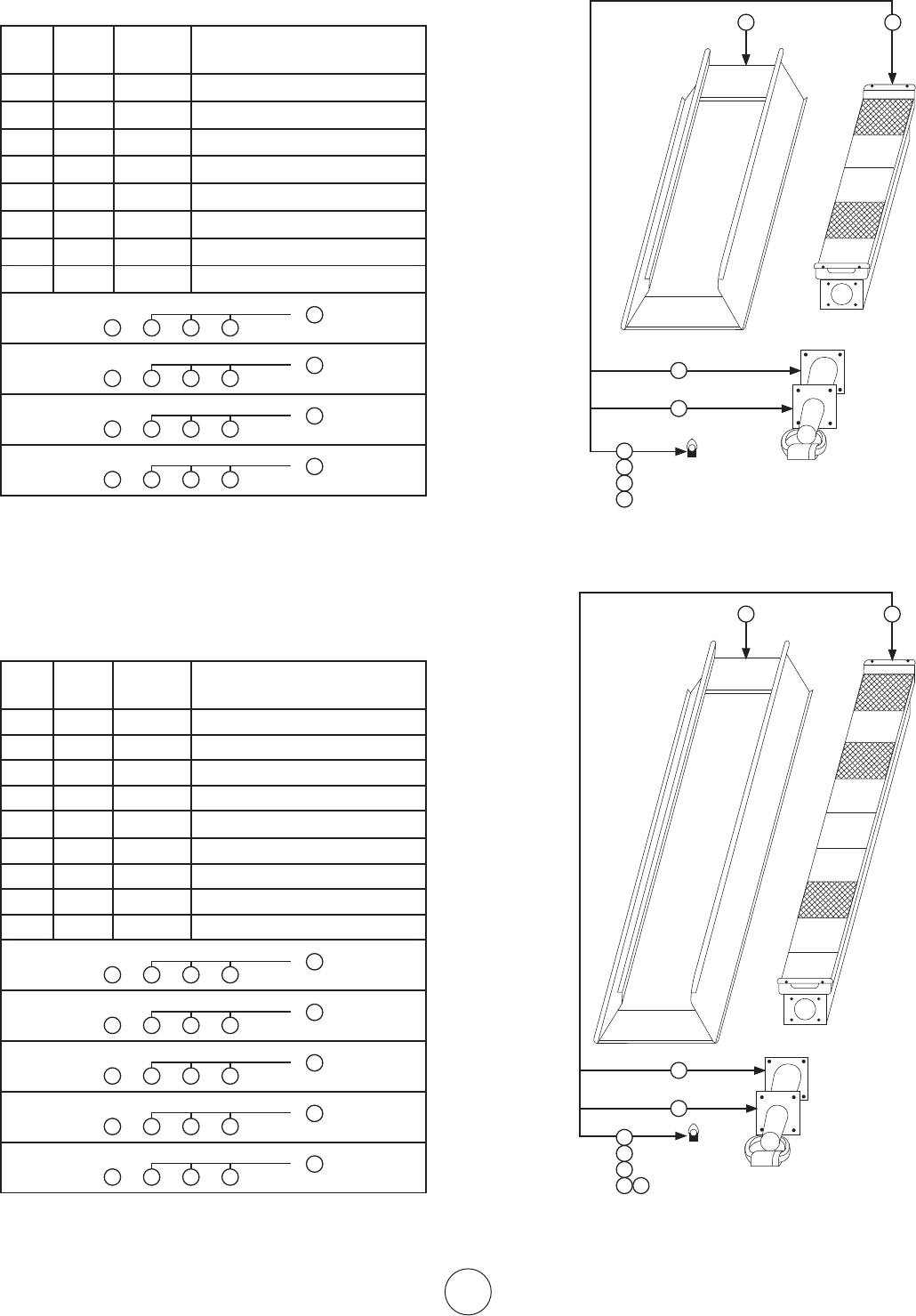
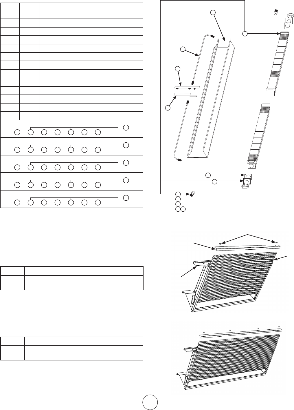
Replacement Parts List For Heaters
4000 Series Models / Less Control
Item
No.
No.
Req’d.
Stock
No.
Description
1 1 00435A ReflectorAssembly
2 1 02523A BurnerAssembly
3 1 03397P Venturi
4 1 05437 Orifice–Br.N.G.4040
5 1 05443 Orifice–Br.N.G.4030
6 1 05449 Orifice–Br.L.P.4040
7 1 05452 Orifice–Br.L.P.4030
8 1 1236 6 Gasket–Venturi
1 3 4 8
4040Nat.Gas
2
or
1 3 5 8
4030Nat.Gas
2
or
1 3 6 8
4040Propane
2
or
1 3 7 8
4030Propane
2
or
Replacement Parts List For Heaters
8000 Series Models / Less Control
Item
No.
No.
Req’d.
StockNo. Description
1 1 00442A ReflectorAssembly
2 1 02524A BurnerAssembly
3 1 03421P Venturi
4 1 05428 Orifice–Br.N.G.8070
5 1 05429 Orifice–Br.N.G.8060
6 1 05430 Orifice–Br.N.G.8050
7 1 05443 Orifice–Br.L.P.8060
8 1 05445 Orifice–Br.L.P.8050
9 1 1236 6 Gasket–Venturi
1 3 4 9
8070Nat.Gas
2
or
1 3 5 9
8060Nat.Gas
2
or
1 3 6 9
8050Nat.Gas
2
or
1 3 7 9
8060Propane
2
or
1 3 8 9
8050Propane
2
or
5
6
7
8
1 2
9
3
5
6
7
8 9
1 2
10
3
8
4
5
6
7
E10
Enerco Group, Inc. |Gas-Fired Infra-Red Space Heaters Operating Instructions and Owner’s Manual
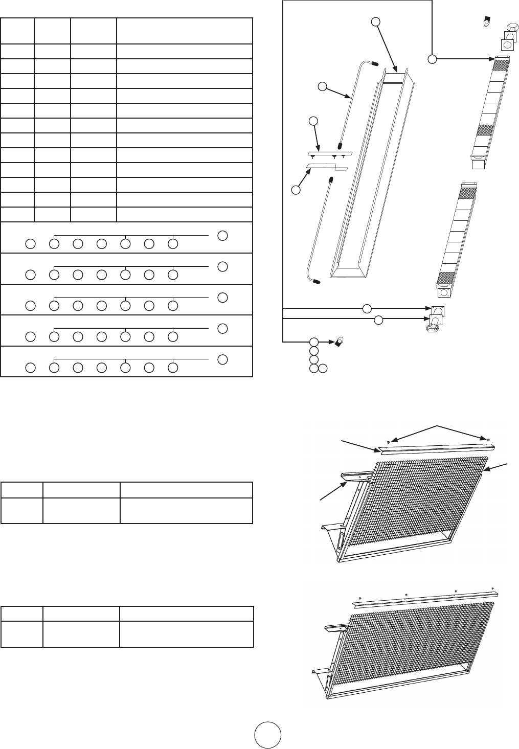
Replacement Parts List For Heaters
9000 Series Models / Less Control
Item
No.
No.
Req’d.
StockNo. Description
1 1 00444A ReflectorAssembly
2 2 02694 BurnerAssembly
3 2 03421P Venturi
4 2 05428 Orifice–Br.N.G.9140
5 2 05429 Orifice–Br.N.G.9120
6 2 05430 Orifice–Br.N.G.9100
7 2 05443 Orifice–Br.L.P.9120
8 2 05445 Orifice–Br.L.P.9100
9 2 06396 ManifoldAssembly
10 2 1236 6 Gasket–Venturi
11 1 14 639 CenterSaddleBracket
12 1 113 81 CenterSupportAss’y
9140Nat.Gas
1 3
10
4
11
9
12
2
or
9120Nat.Gas
1 3
10
7
11
9
12
2
or
9100Nat.Gas
1 3
10
6
11
9
12
2
or
9120Propane
1 3
10
7
119 12
2
or
9100Propane
1 3
10
8
119 12
2
or
1
11
15
14
7
8
9 10
12
6
3
2
4
5
6
7 8
9
10
12
11
F104440 GRIDKIT Grid,Screws,RetentionClip
F104441 RETROGRIDKIT Reflector,Grid,Screws,
RetentionClip,RateTag
Replacement Parts for Retro Grid Kits
4000 Series Models and 8000 Series Models ONLY
F104445 GridKit Grid,Screws,RetentionClip
F104446 RETROGRIDKIT Reflector,Grid,Screws,
RetentionClip,RateTag
Grid
Retention Clip
Screws
Reflector
4000 Series Models
8000 Series Models
8000SERIES
4000SERIES
E 11
Operating Instructions and Owner’s ManualEnerco Group, Inc. | Gas-Fired Infra-Red Space Heaters
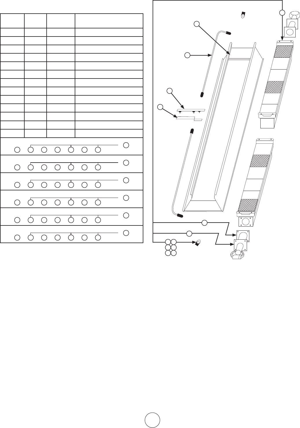
Replacement Parts List For Heaters
9100S Series Models / Less Control
ItemNo.
No.
Req’d.
StockNo. Description
1 1 00443A ReflectorAssembly
2 2 02508A BurnerAssembly
3 2 03421P Venturi
4 2 05431 Orifice–Br.N.G.9100S
5 2 05432 Orifice–Br.N.G.9090
6 2 05437 Orifice–Br.N.G.9080
7 2 05446 Orifice–Br.L.P.9100S
8 2 05447 Orifice–Br.L.P.9090
9 2 05449 Orifice–Br.L.P.9080
10 2 06398 ManifoldAssembly
11 2 1236 6 Gasket–Venturi
12 1 14639 CenterSaddleBracket
13 1 113 81 CenterSupportAssembly
9100SNat.Gas
1 3
11
4
1210 13
2
or
9090Nat.Gas
1 3
11
5
1210 13
2
or
9080Nat.Gas
1 3
11
6
1210 13
2
or
9100SPropane
1 3
13
7
1210 13
2
or
9090Propane
1 3
13
8
1210 13
2
or
9080Propane
1 3
13
9
1210 13
2
or
15
12
1
6 7
8 9
10 11
2
16
3
13
4
5
6 7
8
9
10
11
12
13
E 12
Enerco Group, Inc. |Gas-Fired Infra-Red Space Heaters Operating Instructions and Owner’s Manual
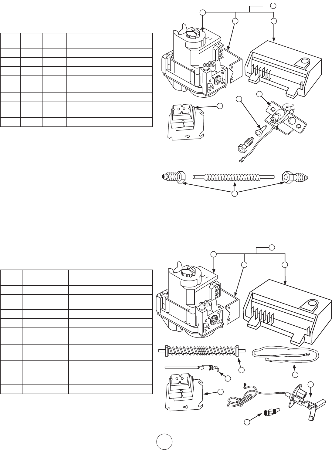
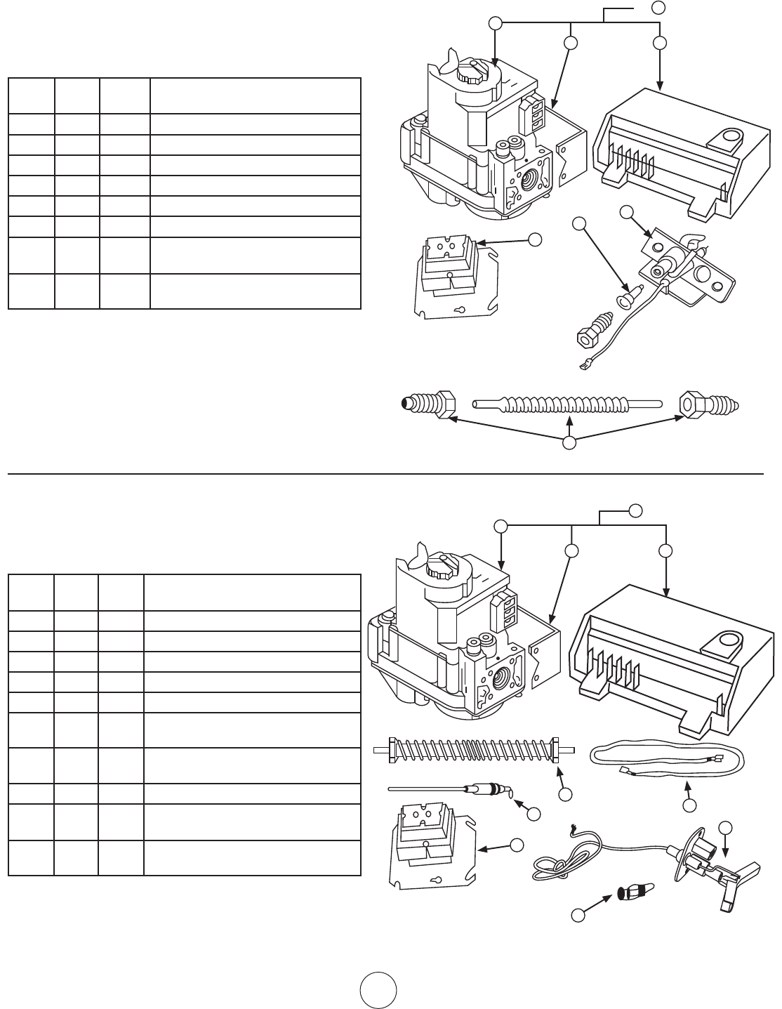
HEAT STAR SERIES 4000SP , 8000SP (NG)
REPLACEMENT PARTS LIST FOR CONTROL
SYSTEM SUFFIX SPARK MODELS
ITEM
NO.
NO.
REQ’D
STOCK
NO.
DESCRIPTION
1 1 00063
IGNITIONMODULE,FENWAL
2 1 00037 GASVALVE-NG/VR8204A2001/SWC
3 1 00228 CONTROLASSY.NG
4 1 05573 ORIFICEPILOTNG.
5 1 08353 TRANSFORMER40VA
6 1 114 0 3 PILOTBURNERASSY.
7 1 14619 BRACKETMTG.A5,745RS,L&
HON.V.
8 1 16437 PILOTTUBEW/FITTINGS
HEAT STAR SERIES 9000SP, 9000SSP (NG)
REPLACEMENT PARTS LIST FOR CONTROL
SYSTEM SUFFIX SPARK MODELS
ITEM
NO.
NO.
REQ’D
STOCK
NO.
DESCRIPTION
1 1 00063
IGNITIONMODULE,FENWAL
2 1 00037
GASVALVENG/VR8204A2001/
SWC
3 1 00228 CONTROLASSY.NG
4 1 05383 ORIFICEPILOT–NG
5 1 08353 TRANSFORMER40VA
6 1 09374 PROBET/C15/32”LONG
7 1 09375
PROBELEAD4000,8000,9000
HTRS.
8 1 14619 PILOTBURNERASSY.
9 1 14 615
BRACKETMTG.A5,745RS,L&
HON.V.
10 1 16453 PILOTTUBEW/FITTINGS
1
3
2
9
5
4
8
6
7
10
5
1
3
2
or
4
6
8
7
E 13
Operating Instructions and Owner’s ManualEnerco Group, Inc. | Gas-Fired Infra-Red Space Heaters
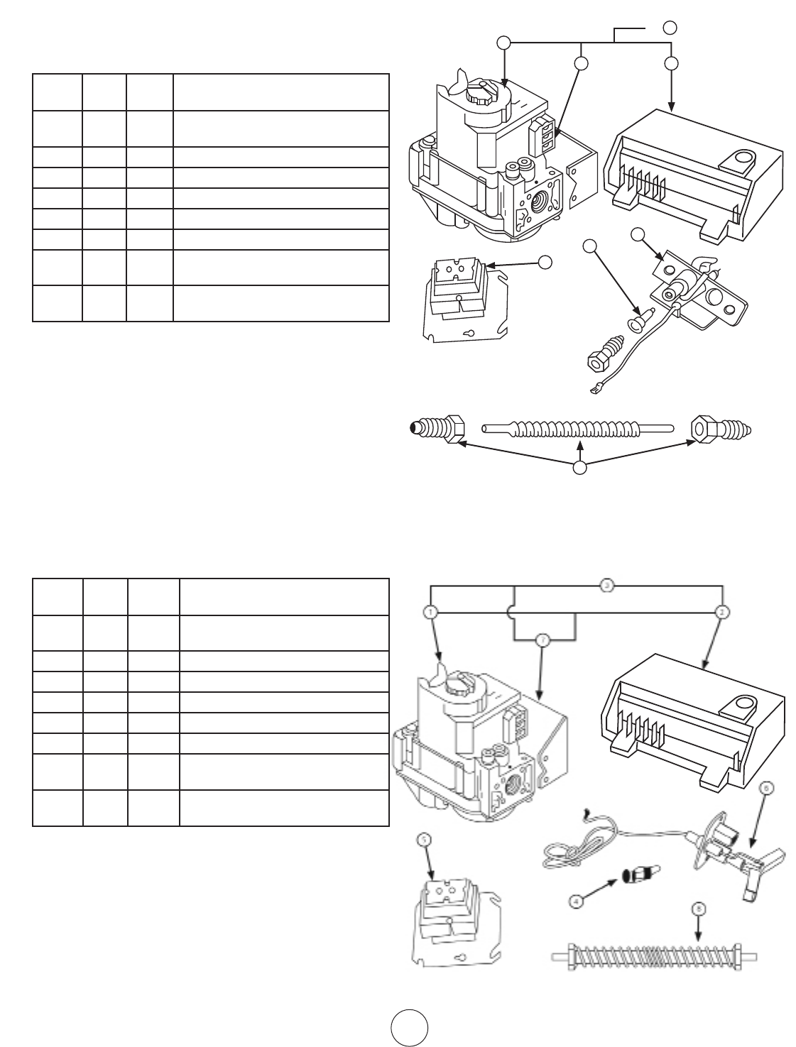
REPLACEMENT PARTS LIST FOR CONTROL
SYSTEM SUFFIX SP
ITEM
NO.
NO.
REQ’D
STOCK
NO.
DESCRIPTION
1 1 00036
GASVALVELP/VR8204A2092/11”
WC
2 1 00063 IGNITIONMODULE,FENWAL
3 1 00329 CONTROLASSY.LP
4 1 05577 ORIFICEPILOT–LP
5 1 08353 TRANSFORMER40VA
6 1 114 0 7 PILOTBURNERASSY.
7 1 14 615
BRACKETMTG.A5,745RS.L.&
HON.V.
8 1 16437 FLEXPILOTTUBEW/FITTINGS
HEAT STAR SERIES 4000SP, 8000SP (LP)
5
3
2
or
4
6
8
7
REPLACEMENT PARTS LIST FOR CONTROL
SYSTEM SUFFIX SP
ITEM
NO.
NO.
REQ’D
STOCK
NO.
DESCRIPTION
1 1 00036
GASVALVELP/VR8204A2092/11”
WC
2 1 00063 IGNITIONMODULE,FENWAL
3 1 00329 CONTROLASSY.LP
4 1 05384 ORIFICEPILOT–LP
5 1 08353 TRANSFORMER40VA
6 1 113 8 5 PILOTBURNERASSY.
7 1 14 615
BRACKETMTG.A5,745RS.L.&
HON.V.
8 1 16425 FLEXPILOTTUBEW/FITTINGS
HEAT STAR SERIES 9000SP, 9000S (LP)
1
2
3
7
5
6
4
8
1
E14
Enerco Group, Inc. |Gas-Fired Infra-Red Space Heaters Operating Instructions and Owner’s Manual
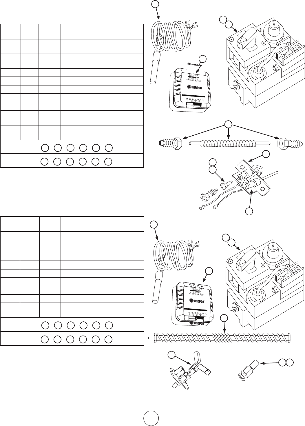
FOR HEAT STAR SERIES 4000, 8000
REPLACEMENT PARTS LIST FOR
CONTROL SYSTEM SUFFIX PPNG & PPLP
ITEM
NO.
NO.
REQ’D
STOCK
NO.
DESCRIPTION
1 1 00024
COMB.GASVALVE(PP)NG.
1/2x1/2NPT
2 1 00025
COMB.GASVALVE(PP)LP.1/2x1/2
NPT
3 1 05577 ORIFICEPILOTLP
4 1 05573 ORIFICEPILOTNG
5 1 09360 THERMOCOUPLEPPHONEYWELL
6 1 10367 THERMOSTAT“PP”HEATSTAR
7 1 114 0 5 PILOT-PP-4K,8KHTRNG
7 1 11408 PILOT-PP-4K,8KHTRLP
8 1 16454 FLEXPILOTTUBEWITHFITTINGS
PPNG
1 4 5 6 7 8
PPLP
2 3 5 6 7 8
1
4
5
6
7
8
2
3
1
5
3
6
2
8
4
5
7
OR HEAT STAR SERIES 9000, 9000S
REPLACEMENT PARTS LIST FOR
CONTROL SYSTEM SUFFIX PPNG & PPLP
ITEM
NO.
NO.
REQ’D
STOCK
NO.
DESCRIPTION
1 1 00024
COMB.GASVALVE(PP)NG.
1/2x1/2NPT
2 1 00025
COMB.GASVALVE(PP)LP.1/2x1/2
NPT
3 1 05384 ORIFICEPILOTLP
4 1 05383 ORIFICEPILOTNG
5 1 09360 THERMOCOUPLEPPHONEYWELL
6 1 10367 THERMOSTAT“PP”HEATSTAR
7 1 113 8 5 PILOTBURNER-9000HTR
8 1 16433 FLEXPILOTTUBEWITHFITTINGS
PPNG
1 4 5 6 7 8
PPLP
2 3 5 6 7 8
NOTE:1–WHENORDERINGSPAREPARTSALWAYSGIVEHEATER
MODELNO.,STOCKNO.,SERIALNO.,ANDTYPEOR
GASUSED.
2–WHENDISASSEMBLINGPARTSFROMHEATERFORRE-
PAIR,CAREFULLYNOTEORIENTATIONOFPARTS,AND
THENREVERSEPROCEDUREWHENASSEMBLING.
1
4
5
6
7
8
2
3
1
5
3
6
2
8
4
5
7
E 15
Operating Instructions and Owner’s ManualEnerco Group, Inc. | Gas-Fired Infra-Red Space Heaters
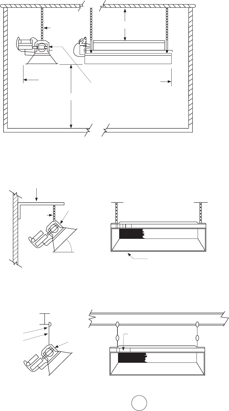
SUGGESTEDHANGINGMETHOD
MODEL:4000,8000,9000,MH40
TYPICAL BEAM MOUNT
FIGURE 4
CEILING
SIDE
WALL
FLOOR
HORIZONTAL MOUNT
BACK
SEEINSTALLATIONINSTRUCTIONSFOR
DETAILEDCLEARANCESINFORMATION
CLEARANCES TO COMBUSTIBLES
BELOW
TOP
BEAMCLAMP
THREADEDROD
WHENANGLEMOUNTING
ELEVATEONLYDESIGNATED
SIDEOFHEATER
FIGURE 5
ANGLEIRON
SEECHAINKIT
#17374OR
THREADEDROD
FROM
HORIZONTAL
MAXIMUM
45°
TYPICAL WALL MOUNT
HEATERSIDEREFLECTORMUST
BEPARALLELTOTHEFLOOR
MOUNTING
SEECHAIN
KIT#17374
ORTHREAD-
ED ROD
F114581HANGING
BRACKETKIT
F114581HANGING
BRACKETKIT
ORCHAIN
KIT17374
RECOMMENDUSING
HEATERHANGING
BRACKETF114581
E16
Enerco Group, Inc. |Gas-Fired Infra-Red Space Heaters Operating Instructions and Owner’s Manual
WARNING: USEONLYMANUFACTURER’SREPLACEMENTPARTS.USE
OFANYOTHERPARTSCOULDCAUSEINJURYORDEATH.REPLACEMENTPARTS
AREONLYAVAILABLEDIRECTFROMTHEFACTORYANDMUSTBEINSTALLEDBY
AQUALIFIEDSERVICEAGENCY.
PARTS ORDERING INFORMATION:
PURCHASING: AccessoriesmaybepurchasedatanyMr.Heater/HeatStarlocaldealer
or direct from the factory
FOR INFORMATION REGARDING SERVICE
PleasecallToll-Free866-447-2194•www.enerco-mrheater.com
Ourofficehoursare8:30AM–5:00PM,EST,MondaythroughFriday.
Emailto:techservice@enerco-mrheater.com
Please include the model number, date of purchase, and description of problem in all
communication.
LIMITED WARRANTY
Thecompanywarrantsthisproducttobefreefromimperfectionsinmaterialorworkmanship,
undernormalandproperuseinaccordancewithinstructionsofTheCompany,foraperiodof
oneyearfromthedateofdeliverytothebuyer.TheCompany,atitsoption,willrepairorreplace
products returned by the buyer to the factory, transportation prepaid within said one year period
andfoundbytheCompanytohaveimperfectionsinmaterialorworkmanship.
Pro-rated10-yearwarrantyontheburnerassemblyonly.
Ifapartisdamagedormissing,callourTechnicalSupportDepartmentat866-447-2194.
AddressanyWarrantyClaimstotheServiceDepartment,EnercoGroup,Inc.,4560W.160thSt.,
Cleveland,Ohio44135.Includeyourname,addressandtelephonenumberandincludedetails
concerningtheclaim.Also,supplyuswiththepurchasedateandthenameandaddressofthe
dealer from whom you purchased our product.
TheforegoingisthefullextentoftheresponsibilityoftheCompany.Therearenoother
warranties,expressorimplied.Specificallythereisnowarrantyoffitnessforaparticularpurpose
andthereisnowarrantyofmerchantability.InnoeventshalltheCompanybeliablefordelay
causedbyimperfections,forconsequentialdamages,orforanychargesoftheexpenseof
anynatureincurredwithoutitswrittenconsent.Thecostofrepairorreplacementshallbethe
exclusiveremedyforanybreachofwarranty.Thereisnowarrantyagainstinfringementofthe
likeandnoimpliedwarrantyarisingfromcourseofdealingorusageoftrade.Thiswarrantywill
not apply to any product which has been repaired or altered outside of the factory in any respect
which in our judgment affects its condition or operation.
Somestatesdonotallowtheexclusionorlimitationofincidentalorconsequentialdamages,so
theabovelimitationorexclusionmaynotapplytoyou.ThisWarrantygivesyouspecificlegal
rights,andyoumayhaveotherrightswhichvaryfromstatetostate.
EnercoGroup,Inc.,reservestherighttomakechangesatanytime,withoutnoticeor
obligation, in colors, specifications, accessories, materials and models.
ENERCOGROUP,INC.,4560W.160THST.,CLEVELAND,OHIO44135•866-447-2194
Mr.HeaterisaregisteredtrademarksofEnercoGroup,Inc.
©2017,EnercoGroup,Inc.Allrightsreserved
ANSI Z83.19a-2011/CSA 2.35a-2011
LANGUAGES
LANGUAGES
OPERATING INSTRUCTIONS AND OWNER’S MANUAL
READ INSTRUCTIONS CAREFULLY: Read and follow all
instructions. Place instructions in a safe place for future
reference. Do not allow anyone who has not read these
instructions to assemble, light, adjust or operate the heater.
HEATSTAR High-Intensity Infrared Heaters
HS4030 HS8070 HS9100
HS4040 HS9080 HS9120
HS8050 HS9090 HS9140
HS8060 HS9100S
MODELS
PRODUCTREGISTRATION:Thankyouforyourpurchase.
Pleaselogintohttp://www.egiregistration.comtoregisteryourproduct.
GUIDE D’UTILISATION ET MANUEL DU PROPRIÉTAIRE
LISEZ SOIGNEUSEMENT LES INSTRUCTIONS :Lisezetsuiveztoutes
lesinstructions.Conservezcesinstructionsdansunendroitsécuritaire
pourvousyréférerultérieurement.Nepermettezpasàquiconque
n’ayantpaslulesprésentesinstructionsd’assembler,d’allumer,de
régleroudefairefonctionnerleradiateur.
Radiateurs infrarouges à forte intensité HEATSTAR
LANGUAGES
MODÈLEN°:
Installateur : Veuillez remettre ce manuel avec l'appareil. Utilisateur : Conservez ce manuel pour vous y référer ultérieurement.
Si les informations contenues dans ce manuel ne sont pas suivies à la
lettre, cela pourrait provoquer un incendie ou une explosion qui pourrai-
causer des dommages à la propriété, des blessures ou des pertes de vie.
AVERTISSEMENT :
— Nepasentreposerniutiliserd'essenceoud'autresvapeursetliquidesinflammablesàproximitéde
cet appareil ou de tout autre appareil.
— QUEFAIRESIVOUSPERCEVEZUNEODEURDEGAZ
• Ouvrezlafenêtre.
• NE PAS tenter d'allumer l'appareil.
• NE PASutiliserlesinterrupteursélectriques.
• NE PAS utiliseruntéléphonedansvotremaison.Appelezimmédiatementvotrefournisseur
degazàpartirdutéléphoned'unvoisin.Suivezlesinstructionsdufournisseurdegaz.
• NE TOUCHEZ àaucuninterrupteurélectrique;n’utilisezaucuntéléphonedansvotreimmeuble.
• L’installationetl'entretiendoiventêtreeffectuésparuninstallateurqualifié,uneagencede
serviceoulefournisseurdegaz.
• Sivousnepouvezpasjoindrevotrefournisseurdegaz,appelezlespompiers.
Ils'agitd'unradiateurnonventiléalimentéaugaznaturel.Ilutilisel'air(oxygène)delazonedanslaquelleil
fonctionne.Ondoitassurerunapportsuffisantd'airdecombustionetdeventilation.Reportez-vousàlapage4.
ENERCOGROUPINC.,4560W.160THST.,CLEVELAND,OHIO44135•866-447-2194
Modèles 4000 et 8000 Modèles 9000
18650-CB
HS4030 HS8070 HS9100
HS4040 HS9080 HS9120
HS8050 HS9090 HS9140
HS8060 HS9100S
F-2
Guided’utilisationetmanueldupropriétaireEnercoGroup,Inc.|Radiateursinfrarougesàforteintensité
TABLE DES MATIÈRES
Informationsgénérales ..............................................................F3
Dégagements ............................................................................F3
Alimentationengaz ...................................................................F3
Pression du gaz ..........................................................................F4
Systèmeélectrique .....................................................................F5
Thermostatetemplacement ......................................................F5
Ventilation .................................................................................F5
Fonctionnement .........................................................................F5
Informationsurlenettoyage ......................................................F5
Thermostat ................................................................................F6
Dépannage ................................................................................F7
Schémadeconnexionducourantdudétecteurdeflamme
pourlessystèmesderectificationdelaflamme. ...................F8
Piècesderechange. ...................................................................F9
Piècesderechangedusystèmedecontrôle. ............................ F 12
AVERTISSEMENT : Unemauvaiseinstallation,
réglage,entretienoumaintenancepeutcauserdes
dommagesmatériels,desblessuresoulamort.Veuillez
lire minutieusement les instructions d'installation,
d'exploitationetd'entretienavantd'installeroud'entretenir
cetéquipement.Pourdel'aideoudesrenseignements
supplémentaires,consultezuninstallateurqualifié,une
agencedeserviceoulefournisseurdegaz.
AVERTISSEMENT : Lorsqu'ilestutilisésans
apportd'airfrais,leradiateurpeutproduireduMONOXYDE
DECARBONE,ungaztoxiqueinodore.OUVREZUNE
FENÊTRED'ENVIRONCINQCENTIMÈTRESPOURPERMETTRE
UNAPPORTD'AIRFRAISLORSQUEVOUSUTILISEZLE
RADIATEUR.
AVERTISSEMENT : Ceradiateurestéquipéd'un
SYSTÈMEDEVEILLEUSEDESÉCURITÉ.NEPASALTÉRERLE
SYSTÈMEDEVEILLEUSEDESÉCURITÉ.
AVERTISSEMENT : Sileradiateurs'éteint,veuillez
assurerunapportd'airfraisavantdelerallumer.Sile
radiateurcontinueàs'éteindre,faites-leréparer.Maintenez
lapropretédubrûleuretdescommandes.Ouvrezlaporte
pendant5minutes.
Maintenirlesdégagementsindiquésàlafigure1ousurlaplaque
signalétiqueduradiateur.
•NEPASUTILISERD'ALLUMETTEOUD'AUTREFLAMMEPOUR
DÉTECTERLESFUITES.
•LAPRESSIOND'ENTRÉEDURADIATEURNEDOITPAS
DÉPASSER0,03KG/CM
2
(½L/PO
2
).
MISE EN GARDE :
Uneintoxicationaumonoxydedecarbonepeutentraîner
la mort.
Intoxication au monoxyde de carbone :
Lespremierssignesd'intoxicationaumonoxydedecarbone
ressemblentauxsymptômesdelagrippe,c.-à-d.des
mauxdetête,desvertigesoudesnausées.Sivousavez
cessymptômes,leradiateurnefonctionnepeut-êtrepas
correctement.Allezrespirerimmédiatementdel'airfrais!
Faitesréparerleradiateur.Certainespersonnessontplus
affectéesparlemonoxydedecarbonequed'autres.Ils'agit
notamment des femmes enceintes, des personnes souffrant
deproblèmescardiaques,demaladiespulmonairesou
d'anémie,lespersonnessousl'influencedel'alcooletcelles
setrouvantàhautealtitude.
MISE EN GARDE :
•Nejamaisconnecterunevalvedegazouunthermostatàla
ligne de tension ou au transformateur.
•Silacouleurinfrarougedelagrilledevientternelorsque
l'appareil de chauffage du bâtiment fonctionne, consultez
votrefournisseurdegazpourajusterlestaillesdela
tuyauterie d'alimentation en gaz.
•Ceradiateurestconçuuniquementpouruneinstallation
d'intérieur!
REMARQUE Lematériauduliantàjointutilisédansce
dispositifderadiateurdégageratemporairementuneodeur
oudelavapeur.Celles-cidisparaîtrontdansles20minutes
environetcettesituationnesereproduiraplusparlasuite.
Reportez-vousàlapage4pourlaventilation.
L'ÉTAT DE CALIFORNIE EXIGE QUE L'AVERTISSEMENT
SUIVANT SOIT FOURNI :
AVERTISSEMENT : Lessous-produitsde
combustionémislorsdel'utilisationdecetappareil
contiennentdumonoxydedecarbone,unproduitchimique
reconnuparl'étatdeCaliforniecommepouvantcauser
lecanceretdesmalformationscongénitales(oud’autres
dommagesausystèmereproducteur).
LANGUES
ANGLAIS
Pages E1 — E16
ESPAGNOL
Pages S1 — S16
FRANÇAIS
Pages F1 — F16
F-3
Guided’utilisationetmanueldupropriétaireEnercoGroup,Inc.|Radiateursinfrarougesàforteintensité
1. INFORMATIONS GÉNÉRALES
a. Votreradiateurestcomplètementassembléetaététesté
enusinepourvérifierlefonctionnementadéquatdeses
systèmesdegazetd'alimentation,telqu'indiquésurla
plaquesignalétique.
b. Avantdeprocéderàl'installation,assurez-vousdevérifierque
l'appareiln'estpasendommagé.Lacompagniedetransport
quialivréleradiateurdoitêtreaviséedetoutdommage
avantl'installation.HEATSTARenverralespiècesderechange
pourlespiècesendommagéesuniquementaprèsavoirreçu
unrapportd'inspectionsignéquiprouvelaresponsabilitéde
la compagnie de transport.
c. Netentezpasdefairefonctionnerleradiateuravecaucun
autregazqueceluiindiquésurlaplaquesignalétiquedu
radiateur.
d. L'installationduradiateurdoitêtreconformeauxcodesdu
bâtimentlocauxou,enl'absencedecodeslocaux,avecla
normeduNationalFuelGasCode,ANSIZ223.1/NFPA54.
AuCanada,reportez-vousàlanormeCAN1-B146.1.
e. UnraccordementdejaugedetestNPTde0,12cm(1/8po)
branchéestsituésurlecontrôledugazduradiateurouun
raccordementNPTestsituéàl'extérieurduCastVenturi.
2. DÉGAGEMENTS Dégagements minimums par rapport aux
matériaux combustibles. (Reportez-vous à la figure 1)
Prévoyezundégagementsuffisantparrapportaux
combustibles,figure1,entrelecôtédecontrôleduradiateur
pourl'entretienetdesdégagementsminimumsau-dessus
etsurlescôtés,ainsiquepourl'alimentationenairde
ventilationetdecombustion.
Undégagementminimumde2,4m(8pi)àpartirdusol
danslesgaragespublics,conformémentàlanormeANSI/
NFPAno88,versionlaplusrécente,ouàlafigure1,selonla
valeurlaplusgrande.AuCanada,reportez-vousauxCodes
d'installation pour les appareils utilisant les combustibles
gazeuxCAN1-B149.1.
Undégagementminimumde3m(10pi)àpartirdubasdu
radiateurjusqu'àl'aile,oul'enceintedumoteur,oùlesavions
sontgarés,etde2,4m(8pi)àpartirdusoldanslesautres
endroitsduhangar,conformémentàlanormeANSI/NFPA
no409,versionlaplusrécente,ouàlafigure1;lavaleurla
plusgrandedoitêtreutilisée.AuCanada,reportez-vousàla
normeACCB149-1-M91.
AVERTISSEMENT : RESPECTERLESDÉGAGEMENTS
ILLUSTRÉSÀLAFIGURE1OUSURLAPLAQUE
SIGNALÉTIQUEDURADIATEURDANSLESINSTALLATIONS
DEGARAGEOÙLESVÉHICULESSTATIONNÉSSONT
DIRECTEMENTAU-DESSOUSDURADIATEUR.
3. SUSPENSION
Leradiateuraquatretrousdemontage,deuxàchaqueextré-
mité,pourfixerlatigeoul'équerredefixationsmétalliqueset
doitêtrefixéd'unemanièresuffisammentsûredansuneposi-
tionindépendantedesconduitesd'alimentationengazeten
électricité.Reportez-vousauxfigures4,5,et7auxpages13
et14pourlessuspensionsrecommandées.
4. ALIMENTATION EN GAZ
Assurerunealimentationengazadéquateàl'entréenominale
dechaqueradiateur,àl'aidedesnormesd'installation
américainesANSI/223surlestuyauxdegazetlesappareils
alimentésaugazdansunbâtiment.LetableauC-3dela
brochure1a/NFPA54indiquelacapacitédestuyauxde
différentsdiamètresetdedifférenteslongueursenpiedscubes
parheurepourlegaznaturelavecunechutedepressionde
0,76cm(0,3po)etunegravitéde0,60.Pourlacapacitédu
gazdepétroleliquéfié(GPL),reportez-vousauxtableauxC-3et
C-15delamêmebrochure.Pourleraccordementrecommandé
dugazauradiateur,reportez-vousàlafigureno5,page15.Au
Canada,reportez-vousauxnormesCAN1-B149.1etCSAB63.
Silesconduitesdegazdoiventêtretestéessouspression
àl'aircomprimé,débranchezchaqueradiateurpouréviter
d'endommagerlescontrôlesetlescapuchonsdesortie.
Aprèsavoirrebranchétouslesradiateurs,videzlesconduites
degazdeleurairetvérifiezquelesraccordementsnefuient
pasenutilisantunesolutionsavonneuse.
AVERTISSEMENT : NEPASUTILISERD'ALLUMETTE
5. EXIGENCES DE TUYAUTERIE
Latuyauterieinstalléedoitseconformerauxcodesetaux
règlementslocauxouàlanormeduNationalFuelGasCode,
ANSIZ223.1(NFPA54),selonlanormequiaprépondérance.
Lorsdel'installationdelatuyauterie,lesexigencessuivantes
doiventêtreprisesencompte:
• Utilisezuntuyaunoirneuf,bienaléséetexemptdecopeaux.
• Appliquezunepâteàjointdebonnequalitésurtousles
filetagesmâlesavantl'assemblage.SilegazPLestutilisé
commecarburant,veillezàcequelapâteàjointsoitrésistante
augazpropane.NEPASUTILISERDERUBANDETEFLON™.
• Avantl'installation,appliquezlapâteàjointsurtousles
filetagesmâles,telqu’illustréàlafigure1.
UTILISEZ UNE QUANTITÉ MODÉRÉE DE PÂTE À JOINT
LAISSEZLESDEUXPREMIERSFILETAGESDÉNUDÉS
Figure 1. Application de la pâte à joint
• Lesfiletagesmâlessurlestuyauxdestinésàêtreinstallésdans
lavalvedegazdoiventsatisfaireauxexigencesdelafigure2.
Lesfiletagespluslongsqueceuxindiquésàlafigure2peuvent
provoquerunedistorsionetundysfonctionnementdelavalve
de gaz.
• Uncollecteurdesédimentsquisatisfaitauxexigences
normalesdelafigure3doitêtreinstallésurlaconduitedela
valvedegaz.
• Unevalved'arrêtdédiéeauradiateurdoitêtreinstalléesurla
conduite d'alimentation en gaz.
¾CM(PO)LONGUEUR
DEFILETAGEMAXIMUM
TUYAUNOIRDE1,2CM
(½PO)
CORPSDELAVALVEÀGAZ
Figure 2.
Exigences de
raccordement
de la valve
de gaz
F-4
Guided’utilisationetmanueldupropriétaireEnercoGroup,Inc.|Radiateursinfrarougesàforteintensité
REMARQUE :
1.Utilisezuniquementunepâteàjointrésistanteauxgazliquéfiés
sur les installations de PL.
2.Lesraccordsillustrésnesontpasinclusavecleradiateur.
Figure 3. Installation normale de la tuyauterie
Collecteur de
sédiments
FIGURE 1
NUMÉRODE
MODÈLE
DÉBITBTU/H.
POSITION
NORMALEDE
MONTAGE
DÉGAGEMENTSPARRAPPORTAUXCOMBUSTIBLES
GAZ
NATUREL PROPANE DESSUS CÔTÉS ARRIÈRE DESSOUS
4030** 30000 30000
Horiz.-45°
76cm(30po) 76cm(30po) 76cm(30po) 1,38m(54po)
4040* 40000 40000
Horiz.-45°
91cm(34po) 76cm(30po) 76cm(30po) 1,7m(68po)
8050** 50000 50000
Horiz.-45°
1,16m(36po) 76cm(30po) 76cm(30po) 2m(78po)
8060* 60000 60000
Horiz.-45°
1,02m(40po) 76cm(30po) 76cm(30po) 2,13m(84po)
8070** 70000 –
Horiz.-45°
1,02m(40po) 76cm(30po) 76cm(30po) 2,13m(84po)
9080** 80000 80000
Horiz.-45°
1,16m(46po) 1,02m(40po) 1,02m(40po) 2,7m(104po)
9090** 90000 90000
Horiz.-45°
1,16m(46po) 1,16m(46po) 1,16m(46po) 2,9m(114po)
9100S* 100000 100000
Horiz.-45°
1,22m(48po) 1,16m(46po) 1,16m(46po) 3m(118po)
9100** 100000 100000
Horiz.-45°
1,12m(44po) 1,02m(40po) 1,02m(40po) 2,7m(104po)
9120 * 120000 120000
Horiz.-45°
1,16m(46po) 1,16m(46po) 1,16m(46po) 2,9m(114po)
9140** 140000 –
Horiz.-45°
1,16m(46po) 1,16m(46po) 1,16m(46po) 2,9m(114po)
*Seulslesmodèlesderadiateursàhauteintensitésuivantssontvendus:4040,8060,9100Set9120
**Ilestpossibled'obtenirlesautresnumérosdemodèleenutilisantlesorificessupplémentairesinclusaveclesradiateurspourmodifierlaproductiondechaleur.
6. PRESSION DU GAZ
Lorsqu'unepressiondegazsupérieureaumaximum
recommandéestmaintenueàlaconduiteprincipaledegaz,
unrégulateurindépendantdoitêtreinstalléenamontdu
radiateur.Reportez-vousàlafigure2pourconnaîtrelapression
maximaleautoriséeenfonctiondumodèleetdutypedegaz.
Voirlaplaquesignalétiqueduradiateurpourconnaître
lapressionminimaled'alimentationengaz«Auxfins
d'ajustementdel'entrée».
Suruneinstallationàplusieursradiateurs,ilestpossible
d'utiliserunrégulateurdegrandecapacitéouunrégulateur
individuelpourchaqueradiateur.Néanmoins,ilest
recommandéd’organiserlesystèmedeconduitedemanière
àcequ’ilformeunebouclecomplète.Communiquezavec
votrereprésentantlocaloul'usinepourconnaîtrelaphasede
conceptionadéquatepourréduirelapressiondugaz.
AVERTISSEMENT : NEPASDÉPASSER0,03KG/CM
2
(½L/PO
2
)DEPRESSIOND'ENTRÉEPOURLESRADIATEURS,
TELQUELEMONTRENTLESFIGURES1ET2
Lesdégagementsauxcombustiblesreprésententunetempératuredesurfacede90°F(32°C)supérieureàlatempératureambiante.Les
matériauxdeconstructionavectoléranceàlachaleurbassepeutêtresoumisàunedégradationàdestempératuresinférieures.Ilestdela
responsabilitédel'installateur
F-5
Guided’utilisationetmanueldupropriétaireEnercoGroup,Inc.|Radiateursinfrarougesàforteintensité
7. SYSTÈME ÉLECTRIQUE
Toutlecâblageexternedoitêtreenconformitéavecles
codesélectriquesexistants.Utilisezleschémafourniavecle
radiateur.Assurez-vousquelescaractéristiquesd'alimentation
électriquecorrespondentàcellesquisontindiquéessur
laplaquesignalétique.L'appareildoitêtrereliéàlaterre
conformémentàlanormeduNationalElectricalCode,
ANSI/NFPA70,dernièrerévision.AuCanada,reportez-vous
auCodecanadiendel'électricitéCSAC22.1
8. THERMOSTAT ET EMPLACEMENT
Assurez-vousquelescaractéristiquesélectriquesdu
thermostatcorrespondentàcellesdescontrôlesduradiateur.
Pourdemeilleursrésultats,lethermostatdevraitêtreinstallé
à1,5m(5pi)au-dessusdusol,oùl'airpeutcirculerlibrement
autourdel'appareil.NEPASINSTALLERlethermostat
directementsurlecôtéfroidd'unmur,dansundébitd'air
directoudirectementau-dessousduradiateurinfrarouge.
9. VENTILATION
a.Lesespacesminimumsd'apportetd'échappementd'air
doiventprévoiraumoins11,3m
3
/min(400pi
3
/min)pour
chaque100000BTU,àl'exceptionquelazoned'infiltration
peutêtreinclusedanslazoned'apport.Leventilateur
d'échappementdoitêtrereliéauthermostatduradiateur.Si
unventilateurautodébrayabled'échappementestutilisé,il
doitêtrecontrôléparlethermostatoul'humidostat.
b.Siuneventilationnaturelle(pargravité)estutiliséepour
l'échappement,lesespacesdoiventêtrerépartisau-dessus
desradiateurs(depréférenceausommetdutoit)etles
zonesd'ouverturenedoiventpasêtreinférieuresà0,20m
2
(300po
2
)pourchaque100000BTU.
10. FONCTIONNEMENT
Aprèsavoirinstallélecâblageélectriqueetlatuyauteriede
gazetavoirvidélesconduitesdegazmenantauxradiateurs,
reportez-vousàlaplaqued'instructiondel'allumagesurle
radiateurpourconnaîtrelaprocédureadéquated'allumage.
11. INFORMATION SUR LE NETTOYAGE
Soufflezàl'aircompriméleVenturietledevantdubrûleur
(pressionmax.de11kg/cm
2
(25l/po
2
));nettoyezégalement
lesorifices(voirlafigure2pourlecalibredeperceuse
adéquat).Pourobtenirdesinstructionsdétailléesd'entretien
etdenettoyage,contactezvotrereprésentantlocaloul'usine.
AVERTISSEMENT : LEMATÉRIAUDELIANTÀJOINT
UTILISÉDANSCEDISPOSITIFDERADIATEURDÉGAGERA
TEMPORAIREMENTUNEODEUROUDELAVAPEUR.UTILISEZ
LAVENTILATION(aOUb)ETCELLES-CIDISPARAÎTRONT
DANSLES20MINUTESENVIRONETCETTESITUATIONNESE
REPRODUIRAPLUSPARLASUITE.
AVERTISSEMENT : NEPASTENTERD'ALLUMERLA
VEILLEUSEÀLAMAINSURLESRADIATEURSÉQUIPÉSD'UN
ALLUMAGEAUTOMATIQUEPARÉTINCELLE.
AVERTISSEMENT : L'ÉTATDECALIFORNIE
EXIGEQUEL'AVERTISSEMENTSUIVANTSOITFOURNI:
LESSOUS-PRODUITSDECOMBUSTIONÉMISLORSDE
L'UTILISATIONDECETAPPAREILCONTIENNENTDU
MONOXYDEDECARBONE,UNPRODUITCHIMIQUERECONNU
PARL'ÉTATDECALIFORNIECOMMEPOUVANTCAUSERLE
CANCERETDESMALFORMATIONSCONGÉNITALES(OU
D’AUTRESDOMMAGESAUSYSTÈMEREPRODUCTEUR).
REMARQUE : UTILISEZLADERNIÈREÉDITIONDE
TOUTESLESNORMESANSIETCANADIENNES.
FIGURE 2
MODÈLE
NO
DÉBITBTU/H. PRESSIONDEL'ALIMENTATIONENGAZ(COLONNED'EAU)
TAILLEDEL'ORIFICE
GAZ MIN. MAX. COLLECTEUR
NATUREL PROPANE NAT. G.P.L. NAT. G.P.L. NAT. G.P.L. NAT. G.P.L.
4030 30000 30000
16,7cm
(6,6po)
28cm
(11po)
35,6cm
(14po)
35,6cm
(14po)
14,2cm
(5,6po)
25,4cm
(10po)
43 52
4040 40000 40000
17,2cm
(6,8po)
28cm
(11po)
35,6cm
(14po)
35,6cm
(14po)
14,7cm
(5,8po)
25,4cm
(10po)
37 49
8050 50000 50000
18cm
(7po)
28cm
(11po)
35,6cm
(14po)
35,6cm
(14po)
11cm
(4,3po)
25,4cm
(10po)
30 45
8060 60000 60000
18cm
(7po)
28cm
(11po)
35,6cm
(14po)
35,6cm
(14po)
14,7cm
(5,8po)
25,4cm
(10po)
29 43
8070 70000 –
18cm
(7po)
–
35,6cm
(14po)
–
15,2cm
(6po)
– 28 –
9080 80000 80000
18cm
(7po)
28cm
(11po)
35,6cm
(14po)
35,6cm
(14po)
14,7cm
(5,8po)
25,4cm
(10po)
37 49
9090 90000 90000
18cm
(7po)
28cm
(11po)
35,6cm
(14po)
35,6cm
(14po)
12,7cm
(5po)
25,4cm
(10po)
32 47
9100S 100000 100000
18cm
(7po)
28cm
(11po)
35,6cm
(14po)
35,6cm
(14po)
12,7cm
(5po)
25,4cm
(10po)
31 46
9100 100000 100000
18cm
(7po)
28cm
(11po)
35,6cm
(14po)
35,6cm
(14po)
11cm
(4,3po)
25,4cm
(10po)
30 45
9120 120000 120000
18cm
(7po)
28cm
(11po)
35,6cm
(14po)
35,6cm
(14po)
14,7cm
(5,8po)
25,4cm
(10po)
29 43
9140 140000 –
18cm
(7po)
–
35,6cm
(14po)
–
14cm
(5,5po)
– 28 –
F-6
Guided’utilisationetmanueldupropriétaireEnercoGroup,Inc.|Radiateursinfrarougesàforteintensité
Figure 5.
Contrôles du
thermostat
14. INSTRUCTIONS D'UTILISATION
DE L’OPÉRATEUR
1. DÉPANNAGE
a. Letableau4énumèrelesproblèmesdusystèmequipourraient
survenirlorsdel'utilisationoudel'entretiendevotreradiateur.
b. Pourdesrenseignementssupplémentaires,consultezleBulletin
techniqueHoneywellinclusdanslaboîteduradiateur.
c. Silessolutionsénuméréesnepermettentpasd'obtenirde
résultat,appelezvotrerevendeurMr.Heaterouleservice
àlaclientèledel'usineau1-866-447-2194.
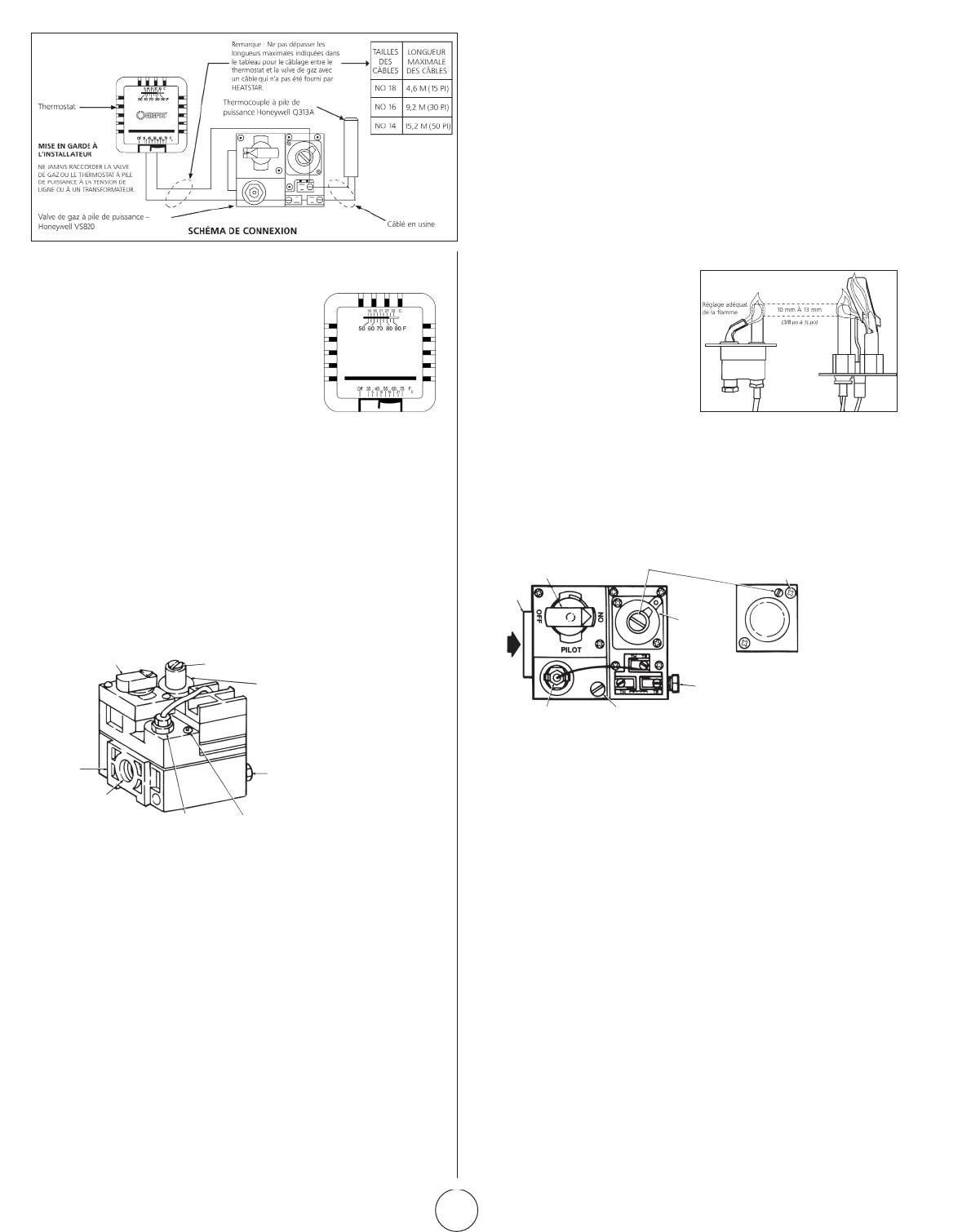
2. AJUSTEMENT DE LA FLAMME DE LA VEILLEUSE
Laflammedelaveilleusedevrait
recouvrirenvironde10à13mm
(3/8à½po)delapointedu
thermocoupleoudugénérateur.
Pourréglerlaflammedela
veilleuse:
12. PROCÉDURE DE DÉMARRAGE
OUVRIRLAVALVEOULESVALVESDEGAZ.
TournezleboutondecontrôledegazmanuelàlapositionPILOT.
Appuyezsurleboutondecontrôledegazmanuel.Àl'aided'une
allumette,allumezlaveilleuse.Voirlafigure6.Maintenezle
boutonpendantenviron30secondespourpermettreàl'airse
trouvantdanslesconduitesdegazdepasseràtraverslaveilleuse
et,unefoisquelaveilleuseestallumée,laissezlethermocouple
chauffersuffisammentpouractiverlavalvedesécuritédansune
positionouverte.
Relâchezleboutondecontrôledugazmanueletréglez-leàla
positionON.Réajustezlethermostatàlatempératuredésirée.
REMARQUE :
LorsdudémarrageinitialdeMR.HEATER,uneodeuret,peut-être,
unpeudevapeursedégagerontduradiateur.C'estlematériaudu
liantàjointquiémetcetteodeuroucettevapeur.Aprèsenviron
20minutes,cetteodeurdisparaîtraetnesereproduiraplus.
13. MISE À l’ARRÊT
1. RéglezlethermostatàOFF.
2. Tournezleboutondecontrôledegazmanuelsurlavalvede
gazàlapositionPILOT.
3. Enfoncezpartiellementleboutonettournez-leàlapositionOFF.
4. Fermezlesvalvesd'alimentationengaz.
RéglezlethermostatàlapositionOFF.Voir
lafigure5.Sileboutondecontrôledegaz
manuelsurlavalvedegazn'estpasenposition
OFF,enfoncezpartiellementleboutonet
tournez-leàlapositionOFF.Voirlafigure6.
Attendez5minutespourpermettreaugaz
quis'estaccumulédanslebrûleurprincipal
desortir(celaestparticulièrementimportant
aprèsl'installation).
a. Retirezlecouvercledelavis
d'ajustementdelaveilleuse.
Reportez-vousàlafigure8.
b. Tournerlavisderéglageintérieuredanslesenshorairepour
diminuer ou dans le sens antihoraire pour augmenter la
flammedelaveilleuse.
c. Toujoursreplacerlecouvercleàvisaprèsl'ajustementetserrer
fermement pour assurer un bon fonctionnement.
Boutonde
contrôlede
gaz manuel
Bordure
de coin
Entrée
de
gaz
Bloc
d'alimentation
delaveilleuse
Ajustementdurégulateur
depression(sousle
couvercleàvis)
Installezune
longuevisdans
lecoinextérieur
Régulateur
de pression
normale
(modèle
«A»)
Régulateur
del'étape
d'ouverture
(modèle
«C»)
Veilleusede
sortie de
gaz(prise
de pression
directement
au-dessous)
Visderéglagedudébit
delaveilleuse(sousle
couvercledelavis)
Figure 8.
Vue du haut
du contrôle
du gaz de
capacité
standard
15. REMPLACEMENT DE L'UNITÉ DE
LA VALVE DE GAZ
a. Retirezlesdeuxfilsdel'unitédelavalvedegazsurlavalvede
contrôledugazportantlamention«PP».
b. Dévissezlavalvedegazdelatuyauteriedegaz.
c. Rebranchezlavalvedegazetlesfilsdel'unitéauxbornes«PP».
N'oubliez pas de laisser un fil du thermostat sur un terminal.
16. FRÉQUENCE DES CONTRÔLES
DE L'OPÉRATEUR
Utilisation intermittente
Lesappareilsquisontutilisésdefaçonsaisonnièredoiventêtrevérifiés
avantlamiseàl’arrêtetdenouveauavantlaprochaineutilisation.
Environnementpoussiéreux,humideoucorrosif.Étantdonnéque
cesenvironnementspeuventdétériorerplusrapidementlecontrôle
dugaz,lesystèmedoitêtrevérifiéplussouvent.
Le contrôle du gaz doit être remplacé si :
a. Ilnefonctionnepascorrectementlorsdelavérificationoudu
dépannage.
b. Leboutondecontrôledugazpeutdifficilementêtretournéou
enfoncé,ous'ilneparvientpasàrebondirunefoisrelâché.
THERMOSTAT
BOUTONDECONTRÔLE
DEGAZMANUEL
BORDURE
DECOIN
ENTRÉE
DEGAZ
AJUSTEMENTDU
RÉGULATEURDEPRESSION
RÉGULATEURDE
PRESSIONNORMALE
(Lapressiond'entréene
doitpasdépasser33cm
(13po)decolonned'eau)
VEILLEUSEDESORTIEDE
GAZ(PRISEDEPRESSION
DIRECTEMENTAU-DESSOUS)
VISDERÉGLAGEDELA
VEILLEUSEDEDÉBIT(SOUS
LECOUVERCLEÀVIS)
BLOCD'ALIMENTATION
DELAVEILLEUSE
Figure 6. Composants
de la valve de gaz
F-7
Guided’utilisationetmanueldupropriétaireEnercoGroup,Inc.|Radiateursinfrarougesàforteintensité
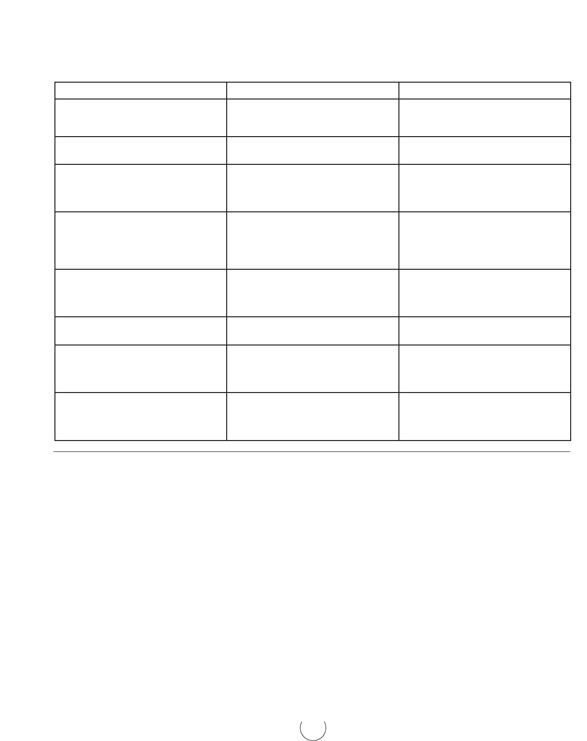
TABLEAU 4. TABLEAU DE DÉPANNAGE
Lesdifférentssymptômesd'undysfonctionnementdusystème,
lesdéfautspossiblesquicausentcessymptômesetlesmesures
correctivessuggéréessontprésentésci-dessoussousformed'un
tableau.Letableausupposequ'unepressiondegazadéquate
estdisponiblepourleradiateuretquelaprocédured'allumage
correspondàcelleindiquéesurlaplaquefixéeauradiateur.
UTILISATION EN HAUTE ALTITUDE
1. Veuillezcontacterl'usinepourunkitdétaillédeconversion
pour une utilisation en haute altitude en fonction de
vosbesoinsspécifiques.1.1Soyezprêtàrépondreaux
questionsdel'usineconcernant:letypedecombustible
del'appareilproposépourlaconversion,lapressiondegaz
disponiblesurlesiteetl'altitudeprécisedusite.
2. «Laconversiondoitêtrefaiteparlereprésentantautorisé
dufabricant,conformémentauxexigencesdufabricantet
conformémentauxexigencesdesautoritésprovincialesou
territorialesayantcompétence.»
3. Leskitsdeconversionpouruneutilisationenhautealtitude
comprendrontuneplaquesignalétiquedehautealtitude
avecdesdonnéeshorodatées,lesorificesoubrûleurs
requispourvosbesoinsspécifiquesetdesinstructions
d'installationsupplémentaires.
4. AuCanada,lesinstallationsderadiateurdehautealtitude
doiventêtreconformesauxdispositionsdeconstruction
applicablesenvertudelanormeactuelleCAN1-2.17,
appareilsalimentésaugazpouruneutilisationenhaute
altitude.
SYMPTÔMES CAUSES SOLUTIONS
Lebrûleurs'allumetrèslentement L’orificedelaveilleuseestpartiellement
bloqué.
Laveilleuseestmalajustée.
Réajusterlaveilleuse
Remplacer
Lebrûleurs'allumetrèslentement.
La couleur reste terne.
L’orificedelaveilleuseestpartiellement
bloqué.
Remplacer
Retourdeflammedubrûleur
(onentendunbruitdegrondementlors
du fonctionnement et la surface de la
grilleencéramiqueestsombre).
Faiblepressiondegaz
Brûleurendommagé
Corriger la pression du conduit ou
appelervotrefournisseurdegaz.
Remplacer
Encrassementdelagrilleencéramique
oudubrûleur(lorsqueneufouaprèsun
nettoyage).
Vérifiezd'abordsil'orificedubrûleurest
endommagé.
Sil'orificedubrûleurn'estpas
endommagé,vérifiezsilecollecteur
estendommagé.
Remplacersiendommagé
Remplacer
Laveilleusenepeutpasêtreallumée. L’orificedelaveilleuseestbloqué.Le
robinet de gaz n'est pas en position.
Lavisderéglagedelaveilleusededébit
degazestpeut-êtrefermée.
Remplacer
Leboutondecontrôledegazdoitêtre
réglésurPILOTetmaintenuenfoncé.
Ouvriretajuster(voirfigure8)
Laveilleuses'allumepuiss'éteint. Thermocoupledéfectueux
Contrôledéfectueux
Remplacer
Remplacer
Laveilleuseresteallumée,maislebrûleur
principal ne s'allume pas.
Fildesserréoumalcâblé
Contrôledéfectueux
Orificedubrûleurbloqué
Serrerlesconnexions,vérifierleschéma
de câblage
Remplacer
Nettoyer ou remplacer l'orifice
Ne s'allume pas.
L’alimentationprincipaleengazestcoupée.
Airdanslaconduitedegaz
Lesconnexionsdecâblessontdesserrées.
Lesconnexionsdecâblessontsales.
Ouvrirlesvalvesmanuelles
Viderlaconduitedegaz
Serrerlesconnexionsdecâbles
Nettoyerlesbornesetfixerlesterminaux

F-8
Guided’utilisationetmanueldupropriétaireEnercoGroup,Inc.|Radiateursinfrarougesàforteintensité
SCHÉMA DE CONNEXION DU COURANT DU DÉTECTEUR DE FLAMME
POUR LES SYSTÈMES DE RECTIFICATION DE FLAMME (DSP -5, A5)
TESTER SI LA ZONE DE MISE À LA TERRE EST ADÉQUATE
Leratioadéquatentreledétecteurdeflammeetlazonede
miseàlaterrenepeutpastoujoursêtredéterminéparun
examenvisuelouunemesurephysique.Unmoyencertainde
vérifierl'installationestdemesurerlecourantdudétecteurde
flammedansdesconditionsréellesd'allumage.Ilestfortement
recommandéquel'installateurmesureledébitdecourantentre
latêtedel'unitédudétecteurdeflammeetlabornesurla
plaquedecontrôle(voirfigure3).Mesurerlecourantavecun
microampèremètredeCCoul'équivalent.Nousrecommandons
unesortierégulièrede0,9microampèreouplus.Undébit
constant de courant de cette grandeur dans des conditions
réellesd'allumageindiquegénéralementquelamiseàlaterre
delaveilleuseestadéquate.
REMARQUE :
1. Liretouteslesfichestechniquesdecontrôlefourniesavecce
radiateur.
2. Vérifiersiledétecteurdeflammeentreencontactavecdes
piècesduradiateur.Ledétecteurdeflammedoitêtreexempt
detoutcontactavecleradiateur.Uncontactavecleradiateur
aurapoureffetdecourt-circuiterledétecteurdeflamme.
3. Laporcelainecraqueléesurledétecteurdeflammeaurapour
effetdecourt-circuiterlecapteur.Remplacerledétecteurde
flamme.
Figure 3–Utilisationd'unmicro-ampèremètrepourtesterlazonedemiseàlaterreadéquate.
GND
V2
FENWALL
IGNITION MODULE
IND/
MV1
V1/PV1
TH/W
SPARK
120VAC
24VAC
24 VOLT
THERMOSTAT
OPTIONAL
LINE VOLTAGE
THERMOSTAT
OPTIONAL
TRANSFORMER
(SHIPPED LOOSE)
GAS VALVE
PV
PV/MV
MV
VALVE
GROUND
MAIN BURNER
PILOT BURNER
SPARK ELECTRODE/FLAME SENSOR
F-9
Guided’utilisationetmanueldupropriétaireEnercoGroup,Inc.|Radiateursinfrarougesàforteintensité
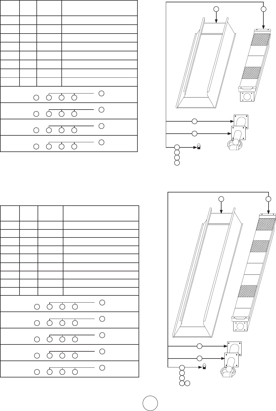
Liste des pièces de rechange pour les radiateurs
Modèles des séries 4000 / Moins de contrôle
Article
no
No
requis
No de
stock
Description
1 1 00435A Réflecteur
2 1 02523A Brûleur
3 1 03397P Venturi
4 1 05437 Orifice–Br.G.N.4040
5 1 05443 Orifice–Br.G.N.4030
6 1 05449 Orifice–Br.G.P.L.4040
7 1 05452 Orifice–Br.G.P.L.4030
8 1 1236 6 Joint–Venturi
1 3 4 8
4040Nat.Gas
2
or
1 3 5 8
4030Nat.Gas
2
or
1 3 6 8
4040Propane
2
or
1 3 7 8
4030Propane
2
or
Liste des pièces de rechange pour les radiateurs
Modèles des séries 8000 / Moins de contrôle
Article
no
No
requis
No de
stock
Description
1 1 00442A Réflecteur
2 1 02524A Brûleur
3 1 03421P Venturi
4 1 05428 Orifice–Br.G.N.8070
5 1 05429 Orifice–Br.G.N.8060
6 1 05430 Orifice–Br.G.N.8050
7 1 05443 Orifice–Br.G.P.L.8060
8 1 05445 Orifice–Br.G.P.L.8050
9 1 1236 6 Joint–Venturi
1 3 4 9
8070Nat.Gas
2
or
1 3 5 9
8060Nat.Gas
2
or
1 3 6 9
8050Nat.Gas
2
or
1 3 7 9
8060Propane
2
or
1 3 8 9
8050Propane
2
or
5
6
7
8
1 2
9
3
5
6
7
8 9
1 2
10
3
5
6
7
8
1 2
9
3
5
6
7
8 9
1 2
10
3
F-10
Guided’utilisationetmanueldupropriétaireEnercoGroup,Inc.|Radiateursinfrarougesàforteintensité
Liste des pièces de rechange pour les radiateurs
Modèles des séries 9000 / Moins de contrôle
Article
no
No
requis
No de
stock
Description
1 1 00444A Réflecteur
2 2 02694 Brûleur
3 2 03421P Venturi
4 2 05428 Orifice–Br.G.N.9140
5 2 05429 Orifice–Br.G.N.9120
6 2 05430 Orifice–Br.G.N.9100
7 2 05443 Orifice–Br.G.P.L.9120
8 2 05445 Orifice–Br.G.P.L.9100
9 2 06396 Collecteur
10 2 1236 6 Joint–Venturi
11 1 14 639 Support de centre de selle
12 1 113 81 Support central
9140Nat.Gas
1 3
10
4
11
9
12
2
or
9120Nat.Gas
1 3
10
7
11
9
12
2
or
9100Nat.Gas
1 3
10
6
11
9
12
2
or
9120Propane
1 3
10
7
119 12
2
or
9100Propane
1 3
10
8
119 12
2
or
1
11
15
14
7
8
9 10
12
6
3
2
4
5
6
7 8
9
10
12
11
F104440 KITGRID Grille,Vis,ClipRetention
F104441 KITRÉTROGRILLE Réflecteur,Grille,Vis,
Clipderétention,Tagdetaux
Pièces de rechange pour kits rétro de grilles
Modèles série 4000 et modèles série 8000 SEULEMENT
F104445 GridKit Grille,Vis,ClipRetention
F104446 RETROGRIDKIT Réflecteur,Grille,Vis,
Clipderétention,Tagdetaux
Grid
Retention Clip
Screws
Reflector
Modèles des séries 4000
Modèles des séries 8000
8000SERIES
4000SERIES

Guided’utilisationetmanueldupropriétaireEnercoGroup,Inc.|Radiateursinfrarougesàforteintensité
F-11
Liste des pièces de rechange pour les radiateurs
Modèles des séries 9100S / Moins de contrôle
Article
no
No
requis
No de
stock
Description
1 1 00443A Réflecteur
2 2 02508A Brûleur
3 2 03421P Venturi
4 2 05431 Orifice–Br.G.N.9100S
5 2 05432 Orifice–Br.G.N.9090
6 2 05437 Orifice–Br.G.N.9080
7 2 05446 Orifice–Br.G.P.L.9100S
8 2 05447 Orifice–Br.G.P.L.9090
9 2 05449 Orifice–Br.G.P.L.9080
10 2 06398 Collecteur
11 2 1236 6 Joint–Venturi
12 1 14639 Support de centre de selle
13 1 113 81 Support central
9100SNat.Gas
1 3
11
4
1210 13
2
or
9090Nat.Gas
1 3
11
5
1210 13
2
or
9080Nat.Gas
1 3
11
6
1210 13
2
or
9100SPropane
1 3
13
7
1210 13
2
or
9090Propane
1 3
13
8
1210 13
2
or
9080Propane
1 3
13
9
1210 13
2
or
15
12
1
6 7
8 9
10 11
2
16
3
13
F-12
Guided’utilisationetmanueldupropriétaireEnercoGroup,Inc.|Radiateursinfrarougesàforteintensité
HEATSTAR 4000SP, 8000SP (NG)
LISTE DES PIÈCES DE RECHANGE POUR LE SYSTÈME
DE CONTRÔLE DE SUFFIXE
Article
no
No
requis
No de
stock
Description
1 1 00063 Moduled'allumageFENWAL
2 1 00037 ValveàgazG.N./VR8204A2001/SWC
3 1 00228 EnsembledecontrôleG.N
4 1 05573 OrificedelaveilleuseG.N.
5 1 08353 Transformateur40va
6 1 114 0 3 Veilleused'allumage
7 1 14615 Supportdemontagea5,745rs,
l.etHon.V.
8 1 16437 Tuyauflexibledelaveilleuseavec
raccords
HEATSTAR 9000SP, 9000SSP (NG)
LISTE DES PIÈCES DE RECHANGE POUR LE SYSTÈME
DE CONTRÔLE DE SUFFIXE
Article
no
No
requis
No de
stock
Description
1 1 00063 Moduled'allumageFENWAL
2 1 00037 ValveàgazG.N/VR8204A2001/SWC
3 1 00228 EnsembledecontrôleG.N.
4 1 05383 OrificedelaveilleuseG.N.
5 1 08353 Transformateur40va
6 1 0 9374
Sondedut/clonguede30mm
(15/32po)
7 1 09375
Fildesondedesappareils4000,
8000,9000.
8 1 113 8 5 Veilleused'allumage
9 1 14615
Supportdemontagea5,745rs,
l.etHon.V.
10 1 16 425
Tuyauflexibledelaveilleuseavec
raccords
1
3
2
9
5
4
8
6
7
10
5
1
3
2
or
4
6
8
7
F-13
Guided’utilisationetmanueldupropriétaireEnercoGroup,Inc.|Radiateursinfrarougesàforteintensité
HEATSTAR 4000SP, 8000SP (LP)
LISTE DES PIÈCES DE RECHANGE POUR LE SYSTÈME
DE CONTRÔLE DE SUFFIXE SP
Article
no
No
requis
No de
stock
Description
1 1 00036
ValveàgazLP/VR8204A2092/
28cm(11po)
2 1 00063
Moduled'allumageFENWAL
3 1 00329 EnsembledecontrôleLP
4 1 05577 Orificedeveilleuse-GPL
5 1 08353 Transformateur40va
6 1 114 0 7 Veilleused'allumage
7 1 14 615
Supportdemontagea5,745rs,
l.etHon.V.
8 1 16 437
Tuyauflexibledelaveilleuseavec
raccords
HEATSTAR 9000SP, 9000SSP (LP)
LISTE DES PIÈCES DE RECHANGE POUR LE SYSTÈME
DE CONTRÔLE DE SUFFIXE SP
Article
no
No
requis
No de
stock
Description
1 1 00036
ValveàgazLP/VR8204A2092/
28cm(11po)
2 1 00063 Moduled'allumageFENWAL
3 1 00329 EnsembledecontrôleLP
4 1 05384 Orificedeveilleuse-LP
5 1 08353 Transformateur40va
6 1 113 8 5 Veilleused'allumage
7 1 14615
Supportdemontagea5,745rs,
l.etHon.V.
8 1 16425
Tuyauflexibledelaveilleuseavec
raccords
5
3
2
or
4
6
8
7
1
F-14
Guided’utilisationetmanueldupropriétaireEnercoGroup,Inc.|Radiateursinfrarougesàforteintensité
POUR LES SÉRIES HEATSTAR 4000, 8000
LISTE DES PIÈCES DE RECHANGE POUR LE SYSTÈME
DE CONTRÔLE DE SUFFIXE NPP, LPP
Article
no
No
requis
No de
stock
Description
1 1 00024
Valveàgazcomb.(PP)G.N.NPT
13mmx13mm(1/2pox1/2po)
2 1 00025
Valveàgazcomb.(PP)G.P.L.NPT
13mmx13mm(1/2pox1/2po)
3 1 05577 Orificedeveilleuse-GPL
4 1 05573 OrificedeveilleuseG.N.
5 1 09360 ThermocouplePPHoneywell
6 1 10367 Thermostat«PP»Heatstar
7 1 114 0 5 Veilleused'allumage-9000HTR
7 1 11408
Tuyauflexibledelaveilleuseavec
raccords
8 1 16425
Tuyauflexibledelaveilleuseavec
raccords
NPP
1 4 5 6 7 8
LPP
2 3 5 6 7 8
1
4
5
6
7
8
2
3
1
5
3
6
2
8
4
5
7
1
4
5
6
7
8
2
3
1
5
3
6
2
8
4
5
7
POUR LES SÉRIES HEATSTAR 9000, 9000S
LISTE DES PIÈCES DE RECHANGE POUR LE SYSTÈME
DE CONTRÔLE DE SUFFIXE NPP, LPP
Article
no
No
requis
No de
stock
Description
1 1 00024
Valveàgazcomb.(PP)G.N.NPT
13mmx13mm(1/2pox1/2po)
2 1 00025
Valveàgazcomb.(PP)G.P.L.NPT
13mmx13mm(1/2pox1/2po)
3 1 05384 Orificedeveilleuse-GPL
4 1 05383 OrificedeveilleuseG.N.
5 1 09360 ThermocouplePPHoneywell
6 1 10367 Thermostat«PP»Heatstar
7 1 113 8 5 Veilleused'allumage-9000HTR
8 1 16425
Tuyauflexibledelaveilleuseavec
raccords
NPP
1 4 5 6 7 8
LPP
2 3 5 6 7 8
REMARQUE:1–ENCASDECOMMANDEDEPIÈCESDE
RECHANGE,TOUJOURSDONNEZLENODE
MODÈLEDURADIATEUR,LENODESTOCK,LE
NODESÉRIEETLETYPEOULEGAZUTILISÉ.
2–LORSDUDÉMONTAGEDURADIATEURPOUR
LARÉPARATION,PORTEZATTENTIONÀ
L'ORIENTATIONDESPIÈCES,PUISREPRODUISEZÀ
L'INVERSELAPROCÉDURELORSDUMONTAGE.
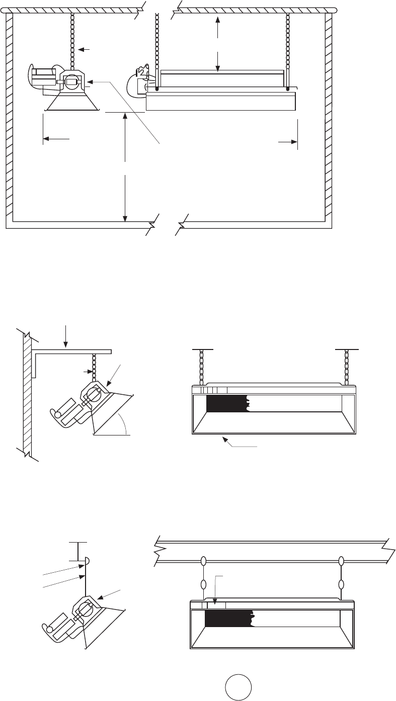
F-15
Guided’utilisationetmanueldupropriétaireEnercoGroup,Inc.|Radiateursinfrarougesàforteintensité
MÉTHODESUGGÉRÉEDESUSPENSION
MODÈLES:4000,8000,9000,MH40
MONTAGE SUR POUTRE NORMAL
FIGURE 4
PLAFOND
CÔTÉ
MUR
PLANCHER
MONTAGE HORIZONTAL
AR-
RIÈRE
VOIRLESINSTRUCTIONSD'INSTALLATIONPOURDES
RENSEIGNEMENTSDÉTAILLÉSSURLESDÉGAGEMENTS.
DÉGAGEMENTS PAR RAPPORT AUX COMBUSTIBLES
DESSOUS
DESSUS
CRAMPONDE
POUTRE
TIGEFILETÉE
DANSUNMONTAGEENANGLE,
SOULEVERUNIQUEMENTLE
CÔTÉINDIQUÉDURADIATEUR
FIGURE 5
ANGLEDEFER
VOIRLEKIT
DECHAÎNES
NO17374OU
LATIGEFILE-
TÉE.
DU
DÉGAGEMENT
HORIZONTAL
MAXIMUM
45°
MONTAGE MURAL NORMAL
LERÉFLECTEURLATÉRALDURADIATEUR
DOITÊTREPARALLÈLEAUPLANCHER.
MONTAGE
VOIRLEKIT
DECHAÎNES
NO17374
OULATIGE
FILETÉE
F114581KITDE
SUPPORTDE
SUSPENSION
F114581KITDE
SUPPORTDE
SUSPENSION
OUKITDE
CHAÎNES
NO17374
L’UTILISATION
DUSUPPORT
DESUSPENSION
F114581DU
RADIATEUREST
RECOMMANDÉE.
F-16
Guided’utilisationetmanueldupropriétaireEnercoGroup,Inc.|Radiateursinfrarougesàforteintensité
AVERTISSEMENT : UTILISERUNIQUEMENTLESPIÈCESDERECHANGE
DUFABRICANT.L’UTILISATIONDETOUTEAUTREPIÈCEPOURRAITCAUSERDESBLESSURES
OULAMORT.LESPIÈCESDERECHANGESONTOFFERTESUNIQUEMENTDIRECTEMENTDE
L’USINEETDOIVENTÊTREINSTALLÉESPARUNEAGENCEQUALIFIÉE.
RENSEIGNEMENTS POUR COMMANDER DES PIÈCES :
POUR ACHETER : Lesaccessoirespeuventêtreachetéschezn'importequelrevendeurlocal
Mr.Heater/HeatStaroudirectementdel'usine.
POUR DES INFORMATIONS SUR LE SERVICE
Veuillezappelersansfraisle866-447-2194•www.enerco-mrheater.com
Nosheuresdebureausontde8h30à17h,fuseauhorairedel'Est,dulundiauvendredi.
Paradresseélectroniqueà:techservice@enerco-mrheater.com
Veuillezinclurelenumérodumodèle,ladated'achatetladescriptionduproblèmedanstoute
communication.
GARANTIE LIMITÉE
LaSociétégarantitqueceproduitestexemptd'imperfectionsd’équipementoudefabrication,
sousutilisationnormaleetappropriée,conformémentauxinstructionsdelaSociété,pour
unepérioded'unanàcompterdeladatedelivraisonàl'acheteur.LaSociété,àsadiscrétion,
répareraouremplaceralesproduitsretournésparl'acheteuràl'usine,letransportpayéd'avance
auseindeladitepérioded'unanetjugésparlaSociétécommeayantdesimperfections
d’équipementoudefabrication.
Garantieauproratade10anssurlebrûleuruniquement.
Siunarticleestendommagéoumanquant,appeleznotreservicedesoutientechniqueau
866-447-2194.
Adresseztouteréclamationaudépartementduserviceàlaclientèle,EnercoGroup,Inc.,
4560W.160thSt.,Cleveland,Ohio44135.Inclurevotrenom,adresseetnumérodetéléphone
etlesdétailsconcernantlaréclamation.Nousfournirégalementladated'achatetlenomet
l'adresseduconcessionnaireauprèsduquelvousavezacheténotreproduit.
CequiprécèderelèveentièrementdelaresponsabilitédelaSociété.Iln'existeaucuneautre
garantie,expliciteouimplicite.Plusprécisément,iln'existeaucunegarantied'adéquationàun
usageparticulieretaucunegarantiedequalitémarchande.EnaucuncaslaSociéténesera
responsabled'unretardcauséparlesimperfections,pourlesdommagesindirectsoudesfraisde
toutenatureengagéssanssonconsentementécrit.Lecoûtdelaréparationouduremplacement
doitêtrelaseuleréparationpourtouteviolationdelagarantie.Iln'yapasdegarantiecontrela
violationanalogueetaucunegarantieimplicitedécoulantducoursdelatransactionoud'usagesdu
commerce.Cettegarantienes'appliqueàaucunproduitquiaétéréparéoumodifiéendehorsde
l'usineàtoutégardcequi,selonnotrejugement,affecteraitsonétatousonfonctionnement.
CertainsÉtatsnepermettentpasl'exclusionoulalimitationdesdommagesfortuitsouconsécutifs,
desortequelalimitationoul'exclusionpeutnepass'appliqueràvous.Cettegarantievousdonne
desdroitslégauxspécifiques,etvouspouvezavoird'autresdroitsquivarientselonlesÉtats.
EnercoGroup,Inc.seréserveledroitdemodifierentouttemps,sanspréavisniobligation,
lescouleurs,spécifications,accessoires,matériauxetmodèles.
ENERCOGROUP,INC.,4560W.160THST.,CLEVELAND,OHIO44135•866-447-2194
Mr.HeaterestunemarquedéposéedeEnercoGroup,Inc
©2017,EnercoGroup,Inc.Tousdroitsréservés.
ANSI Z83.19a-2011/CSA 2.35a-2011
LANGUAGES
LANGUAGES
ENREGISTREMENTDUPRODUIT:Nousvousremercionspourvotreachat.
Veuillezvousconnecteràhttp://www.egiregistration.compourenregistrervotreproduit.
GUIDE D’UTILISATION ET MANUEL DU PROPRIÉTAIRE
LISEZ SOIGNEUSEMENT LES INSTRUCTIONS :Lisezetsuiveztoutes
lesinstructions.Conservezcesinstructionsdansunendroitsécuritaire
pourvousyréférerultérieurement.Nepermettezpasàquiconque
n’ayantpaslulesprésentesinstructionsd’assembler,d’allumer,de
régleroudefairefonctionnerleradiateur.
Radiateurs infrarouges à forte intensité HEATSTAR
MODÈLEN°:
HS4030 HS8070 HS9100
HS4040 HS9080 HS9120
HS8050 HS9090 HS9140
HS8060 HS9100S
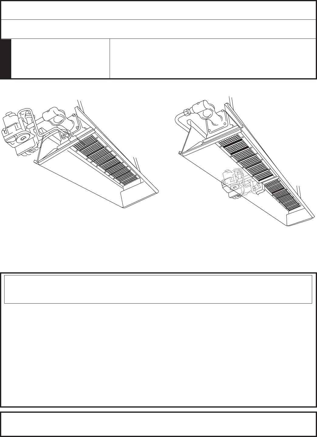
LANGUAGES
INSTRUCCIONES DE USO Y MANUAL DEL USUARIO
LEA CUIDADOSAMENTE LAS INSTRUCCIONES: Lea y siga todas
lasinstrucciones.Conserveestasinstruccionesenunlugarseguro
parafuturareferencia.Nopermitaquenadiequenohayaleído
estas instrucciones arme, encienda, ajuste o use el calentador.
Calentadores infrarrojos de alta intensidad HEATSTAR
MODELOS
Instalador: Deje este manual junto con el artefacto. Consumidor: Conserve este manual para referencia futura.
Si no se siguen al pie de la letra las instrucciones de este manual,
podría producirse un incendio o una explosión que provocaría daños
materiales, lesiones o muertes.
ADVERTENCIA:
— Noalmaceneniutilicegasolinaniningúnotrovapornilíquidoinflamablecercadeestenideningúnotro
artefacto.
— QUÉHACERSIDETECTAOLORAGAS
• Abralasventanas
• NOintenteencenderningúnartefacto.
• NOutiliceinterruptoreseléctricos.
• NOutiliceningúnteléfonoenlacasa.Llameinmediatamentealproveedordegaslocaldesdeel
teléfonodeunvecino.Sigalasinstruccionesdelproveedordegas.
• NOtoqueningúninterruptoreléctrico;noutiliceelteléfonoensuvivienda.
• Lainstalaciónyelserviciodebenserrealizadosporuninstalador,unaagenciadeservicios,
ounproveedordegascalificados.
• Sinopuedecomunicarseconelproveedordegas,llamealDepartamentodebomberos.
Estecalentadoragasnotieneunafuentepropiadeventilación.Utilizaelaire(oxígeno)deláreaenlacualse
emplea.Debesuministrarseelairenecesarioparalaventilaciónylacombustión.Consultelapágina4.
ENERCOGROUPINC.,4560W.160THST.,CLEVELAND,OHIO44135•866-447-2194
Modelos 4000 y 8000 Modelos 9000
18650-CB
HS4030 HS8070 HS9100
HS4040 HS9080 HS9120
HS8050 HS9090 HS9140
HS8060 HS9100S
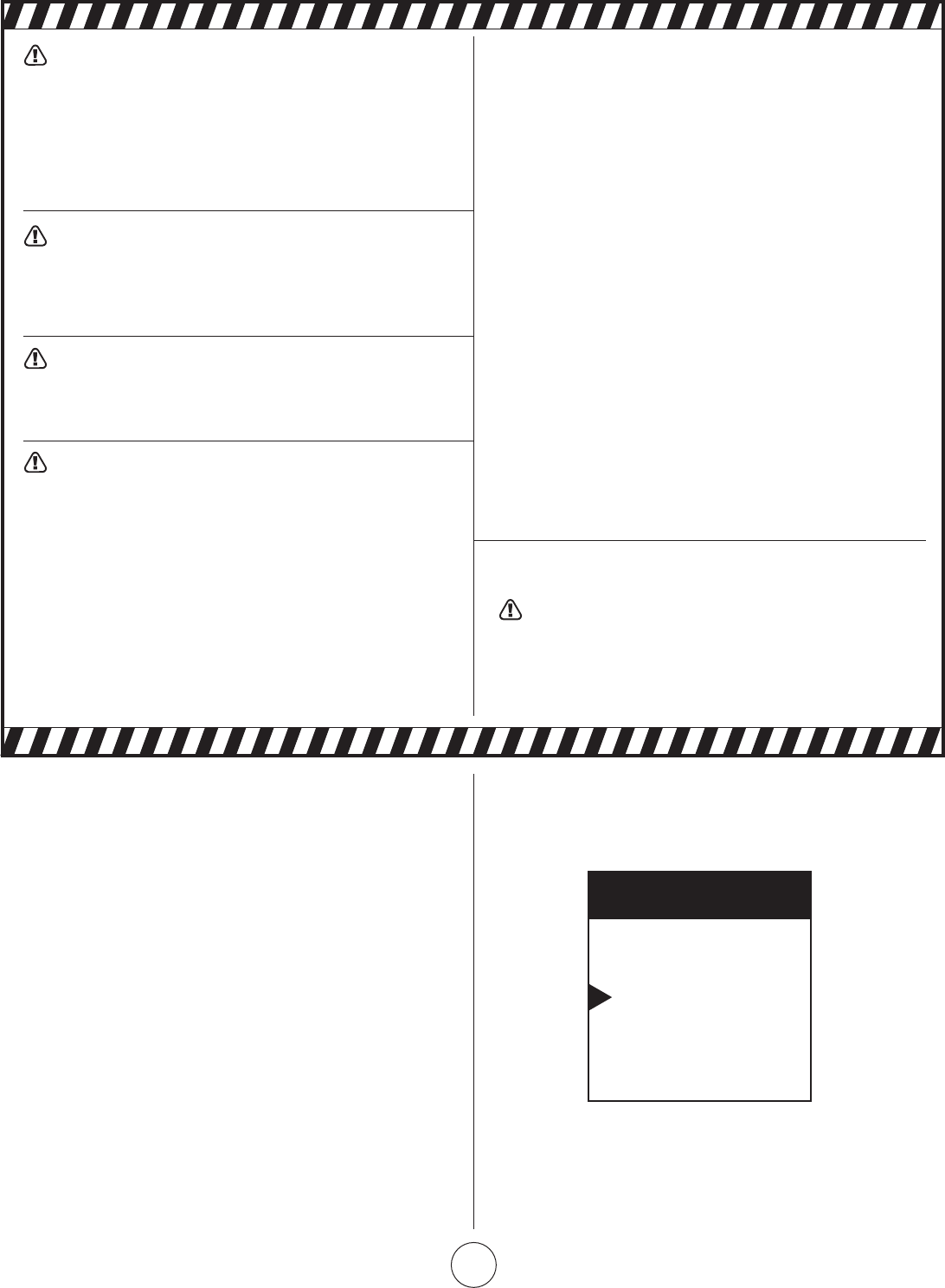
S-2
EnercoGroup,Inc.|Calentadoresinfrarrojosdealtaintensidad Instruccionesdeusoymanualdelusuario
CONTENIDOS
Informacióngeneral .................................................................. S3
Distancias ................................................................................. S3
Suministro de gas ..................................................................... S3
Presióndegas .......................................................................... S4
Electricidad ............................................................................... S5
Termostatoyubicación ............................................................. S5
Ventilación ................................................................................ S5
Funcionamiento ........................................................................ S5
Informacióndelimpieza ............................................................ S5
Termostato ............................................................................... S6
Resolucióndeproblemas .......................................................... S7
Diagramadeconexióndelacorrientedelavarillade
lallamaparalossistemasderectificacióndellamas ............ S8
Repuestos ................................................................................. S9
Repuestos para el sistema de control ........................................S12
ADVERTENCIA: Lainstalación,elajuste,la
alteración,lasreparacionesoelmantenimientoinadecuados
puedenprovocardañosmateriales,lesionesomuertes.
Leacuidadosamentelasinstruccionesdeinstalación,uso
ymantenimientoantesdeinstalarorepararesteequipo.
Paraobtenerasistenciaoinformaciónadicional,consulte
conuninstalador,unaagenciadereparaciónoun
proveedordegascalificados.
ADVERTENCIA: Cuando se utiliza sin aire fresco,
esposiblequeelcalentadordespidaMONÓXIDODE
CARBONO,ungasvenenosoinodoro.ABRALAVENTANA
UNAODOSPULGADASPARAQUECORRAAIREFRESCO
CUANDOUTILICEELCALENTADOR.
ADVERTENCIA: Estecalentadorestáequipado
conunSISTEMADESEGURIDADDEENCENDIDODEL
PILOTO.NOMODIFIQUEELSISTEMADESEGURIDADDE
ENCENDIDODELPILOTO.
ADVERTENCIA: Sielcalentadorseapaga,novuelva
a encenderlo sin antes dejar correr aire fresco. Si el calentador
sigueapagándose,hágaloreparar.Mantengaelquemador
yelcontrollimpios.Abralapuertadurante5minutos.
Mantengadistancia,comosemuestraenlaFigura1oenlaplaca
del calentador.
•NOUTILICEFÓSFOROSNININGUNAOTRALLAMAPARA
VERIFICARLASFUGAS.
•NOEXCEDALOS3,44kPa(1/2PSI)DEPRESIÓNDE
ENTRADAALCALENTADOR.
PELIGRO:
Laintoxicaciónconmonóxidodecarbonopuedellevara
la muerte.
Intoxicación con monóxido de carbono:
Losprimerossíntomasdelaintoxicaciónconmonóxidode
carbonosongripeydolordecabeza,mareosonáuseas.
Sipresentaalgunodeestossíntomas,puedeserqueel
calentadornoestéfuncionandocorrectamente.Tomeaire
frescodeinmediato.Llamealpersonalcalificadoparaquele
realiceelserviciodemantenimientoalcalentador.Algunas
personassevenmásafectadasporelmonóxidodecarbono
queotras.Estoincluyemujeresembarazadas,personascon
problemascardíacosopulmonares,personasconanemia,
personasqueestánbajolainfluenciadelalcoholyaquellas
queseencuentranenaltitudeselevadas.
CUIDADO:
•Nuncaconectelaválvuladegasoeltermostatoaunvoltaje
delíneaoauntransformador.
•Sielcolorinfrarrojodelarejillaseempalidececuandoel
calentadordeledificioestáfuncionando,consulteconel
proveedordegassobreeltamañocorrectodelatuberíade
suministro de gas.
• Estecalentadoresaptosoloparaunainstalacióneninteriores.
NOTA El material de las juntas utilizado en el armado de este
calentadoremitirá,momentáneamente,unolorovapor.
Estoserevertiráenaproximadamente20minutosyluego
novolveráasuceder.Consultelapágina4paraobtener
informaciónsobrelaventilación.
EL ESTADO DE CALIFORNIA EXIGE LA SIGUIENTE
ADVERTENCIA:
ADVERTENCIA: Unadelassustanciasquese
desprendeenlacombustiónalusaresteequipoesel
monóxidodecarbono,uncompuestoquímicoquede
acuerdoconelestadodeCaliforniaproducecáncery
defectosdenacimiento(uotrosdañosreproductivos).
IDIOMAS
INGLÉS
Páginas E1 — E16
ESPAÑOL
Páginas S1 — S16
FRANCÉS
Páginas F1 — F16
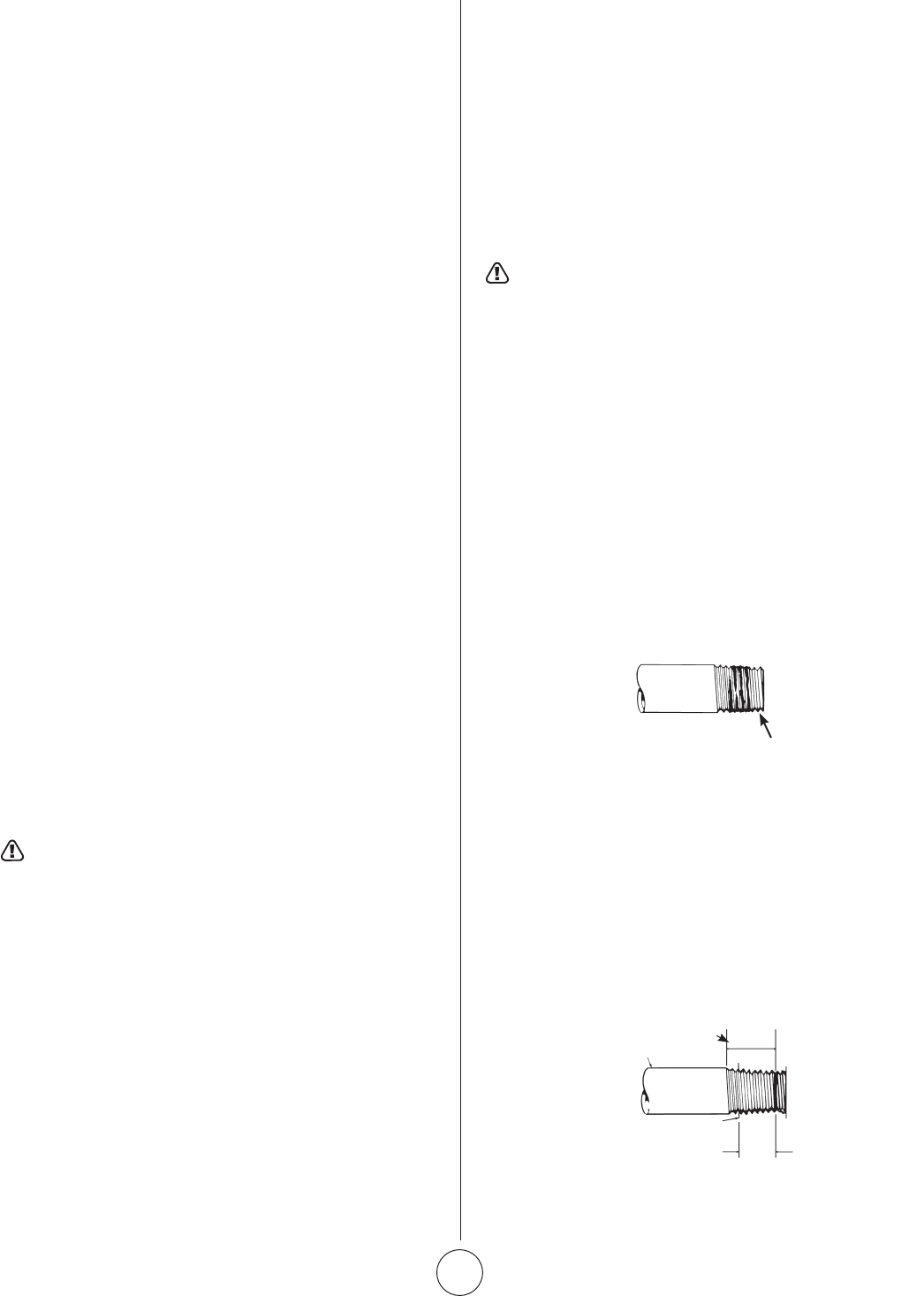
S-3
EnercoGroup,Inc.|Calentadoresinfrarrojosdealtaintensidad Instruccionesdeusoymanualdelusuario
1. INFORMACIÓN GENERAL
a. Elcalentadorvienecompletamentearmadoyselo
pruebaenlafábricaparaverificarqueelgasylaentrada
indicados en la placa sean correctos.
b. Antesdeseguirconlainstalación,verifiquequelaunidad
noestédañada.Debenotificaralacompañíadetransporte
queenvíeelcalentadoracercadecualquierdañoantesde
lainstalación.HEATSTARenviarárepuestosparalaspartes
dañadassolamentedespuésderecibiruninformede
inspecciónfirmadoparademostrarlaresponsabilidaddela
compañíadetransporte.
c. Nointenteusarelcalentadorconningúnotrogasquenosea
elqueseindicaenlaplacadelcalentador.
d. Lainstalacióndelcalentadordebecumplirconloscódigosde
fabricaciónlocales,oenausenciadedichoscódigos,conel
Reglamentonacionaldecombustiblegaseoso,ANSIZ223.1/
NFPA54.EnCanadá,consulteCAN1-B146.1.
e. Laconexióndemedicióndepruebaconectadade0,32cm
(1/8pulgadas)N.P.T.estáubicadaenelcontroldegasdel
calentadorounaconexiónN.P.T.estáubicadaenlaparte
exteriordelCastVenturi.
2. DISTANCIAS Distancias mínimas a combustibles.
(Consulte la Figura 1)
Proporcione distancias adecuadas a los combustibles.
Figura1,entreelextremodecontroldelcalentadorpara
sumantenimientoyelmínimoenlapartesuperioryalos
costadosparaquehayaventilaciónysuministrodeairede
combustión.
Distanciamínimade2,43m(8pies)porencimadelpisoen
garajespúblicosdeacuerdoconANSI/NFPAN.º88,última
edición,oconlaFigura1,laqueseamásgrande.EnCanadá
consulteCAN1-B149.1Códigosdeinstalacióndeartefactos
decombustiónagas.
Distanciamínimade3m(10pies)desdelaparteinferiordel
calentador hasta la parte superior del ala o del recinto del
motor,dondeseguardanlosaviones,yde2,43m(8pies)
porencimadelpisoenotrasáreasdelhangardeacuerdocon
ANSI/NFPAN.º409,últimaedición,oconlaFigura1;sedebe
utilizarladimensiónmásgrandedeANSI/NFPAN.º409ola
Figura1.EnCanadá,consulteCCAB149-1-M91.
ADVERTENCIA: MANTENGALASDISTANCIAS
COMOMUESTRALAFIGURA1OLAPLACADEL
CALENTADOR,ENINSTALACIONESENGARAJESDONDE
LOSVEHÍCULOSESTACIONADOSSEENCUENTRAN
DIRECTAMENTEDEBAJODELCALENTADOR.
3. SUSPENSIÓN
El calentador tiene cuatro orificios de montaje, dos en cada
extremo,parasujetarlavarillaolossoportesangulares
de hierro y se debe fijar de manera segura y adecuada
independientementedelastuberíasdesuministroeléctricoy
degas.ConsultelasFiguras4,5y7enlaspáginas13y14para
obtenerinformaciónsobrelassuspensionesrecomendadas.
4. SUMINISTRO DE GAS
Proporcione el suministro de gas adecuado para la entrada
especificadadecadacalentadormediantelainstalación
estándaramericanadetuberíasdegasyartefactosagas
enedificiosANSI/223.1a/PanfletodeNFPA54,laTabla
C-3muestralacapacidaddelastuberíasdediferentes
diámetrosylongitudesenpiescúbicosporhoraparagas
naturalconunacaídadepresiónde0,76cm(0,3pulgadas),
unagravedadespecíficade0,60.Paraobtenerinformación
sobrelacapacidaddegaslicuadodelpetróleo(liquefied
Petroleum,LP),consultelasTablasC-3yC-15delmismo
panfleto.Paraobtenerinformaciónsobrelaconexióndegas
recomendadaparaelcalentador,consultelaFiguraN.º5,en
lapágina15.EnCanadá,consulteCAN1-B149.1yCSAB63.
Silastuberíasdegassevanaprobarbajopresiónconaire
comprimido,desconectetodosloscalentadoresparaevitar
quesedañeelcontrolyquesesalganlastapas.Despuésde
volveraconectartodosloscalentadores,purguelastuberías
degasdeaireyverifiquetodaslasconexionesconuna
solucióndejabónparaasegurarsedequenohayafugas.
ADVERTENCIA: NOUTILICEFÓSFOROSNININGUNA
OTRALLAMAPARAVERIFICARLASFUGAS.
7. ELECTRICIDAD
5. REQUISITOS DE LAS TUBERÍAS
Todaslastuberíasinstaladasdebencumplirconloscódigosylas
ordenanzas locales o con el Reglamento nacional de combustible
gaseoso,ANSIZ223.1(NFPA54),elquetengaprioridad.Cuando
instalelatubería,debetenerencuentalossiguientesrequisitos:
• Utilicelanuevatuberíanegraadecuadamenteescariadasin
virutas.
• Coloqueuncompuestoparatuberíasdebuenacalidaden
todas las roscas macho antes del armado. Si el gas L.P. es el
combustible,asegúresedequeelcompuestoparatuberíassea
resistentealgasL.P.NOUTILICEcintaTEFLON™.
• Antesdelainstalación,coloquecompuestosparatuberíasen
todaslasroscasmacho,comosemuestraenlaFigura1.
UTILICE UNA CANTIDAD MODERADA DE PEGAMENTO
PARA TUBERÍAS
DEJELAS2PRIMERASROSCASSINPEGAMENTO
Figura 1. Colocación de compuestos para tuberías
• Lasroscasmachosdelatuberíaqueseinstalaránenlaválvula
degasdebencumplirconlosrequisitosdelaFigura2.Las
roscasmáslargasquelasquesemuestranenlafigurapodrían
hacerquelaválvuladegassedeformeyfuncionemal.
• Sedebeinstalarunseparadordesedimentosquecumpla
conlosrequisitostípicosdelaFigura3enlatuberíaala
válvuladegas.
• Sedebeinstalarunaválvuladecierreexclusivaparael
calentadorenlatuberíadesuministrodegas.
LONGITUDMÁXIMA
DELAROSCA¾"
TUBERÍANEGRADE½"
CUERPODELAVÁLVULADEGAS
Figura 2.
Requisitos de la
conexión de la
válvula de gas

S-4
EnercoGroup,Inc.|Calentadoresinfrarrojosdealtaintensidad Instruccionesdeusoymanualdelusuario
NOTA:
1.Utilicesolouncompuestoparatuberíasquesearesistentealos
gases licuados en las instalaciones de L.P.
2.Losacoplesquesemuestrannoestánincluidosenelcalentador.
Figura 3. Instalación típica de las tuberías
Separador de
sedimentos
FIGURA 1
N.° DE
MODELO
ESPECIFICACIÓN
DEBTU/HR.
POSICIÓN
NORMALDE
MONTAJE
DISTANCIAACOMBUSTIBLES
GAS
NATURAL PROPANO SUPERIOR COSTADOS POSTERIOR INFERIOR
4030** 30.000 30.000
Horiz.-45°
76cm(30") 76cm(30") 76cm(30") 1,38m(54")
4040* 40.000 40.000
Horiz.-45°
91cm(34") 76cm(30") 76cm(30") 1,7m(68")
8050** 50.000 50.000
Horiz.-45°
1,16m(36") 76cm(30") 76cm(30") 2m(78")
8060* 60.000 60.000
Horiz.-45°
1,02m(40") 76cm(30") 76cm(30") 2,13m(84")
8070** 70.000 –
Horiz.-45°
1,02m(40") 76cm(30") 76cm(30") 2,13m(84")
9080** 80.000 80.000
Horiz.-45°
1,16m(46") 1,02m(40") 1,02m(40") 2,7m(104")
9090** 90.000 90.000
Horiz.-45°
1,16m(46") 1,16m(46") 1,16m(46") 2,9m(114")
9100S* 100.000 100.000
Horiz.-45°
1,22m(48") 1,16m(46") 1,16m(46") 3m(118")
9100** 100.000 100.000
Horiz.-45°
1,12m(44") 1,02m(40") 1,02m(40") 2,7m(104")
9120 * 120.000 120.000
Horiz.-45°
1,16m(46") 1,16m(46") 1,16m(46") 2,9m(114")
9140** 140.000 –
Horiz.-45°
1,16m(46") 1,16m(46") 1,16m(46") 2,9m(114")
*Loscalentadoresdealtaintensidadquesevendensonsólo4040,8060,9100Sy9120
**Losdiferentesnúmerosdemodelosealcanzanalusarlosorificiossuplementariosincluidosconloscalentadoresparacambiarelniveldecalor.
6. PRESIÓN DE GAS
Cuandosemantieneunapresióndegasmásaltaquela
máximarecomendadaenlatuberíaprincipaldegas,sedebe
instalarotroreguladorantesqueelcalentador.Consultela
Figura2paraobtenerinformaciónsobrelapresiónmáxima
permitida para el modelo y el gas indicados.
Consulte la placa de especificaciones del calentador para
obtenerinformaciónsobrelapresiónmínimadelsuministro
degas“paraajustarlaentrada”
Paraunainstalacióndevarioscalentadores,esposibleutilizar
unreguladordegrancapacidadounreguladorindividual
para cada calentador. Sin embargo, se recomienda hacer de
todoelsistemadetuberíasuncircuito.Póngaseencontacto
con su representante local o con el fabricante para obtener
informaciónsobrelafasedediseñodereduccióndela
presióndegasadecuada.
ADVERTENCIA: NOEXCEDALOS3,44kPa(½P.S.I.)
DEPRESIÓNDEENTRADAALOSCALENTADORESQUESE
MUESTRANENLASFIGURAS1Y2
Lasseparacionesaloscombustiblesrepresentanunatemperaturasuperficialde90°F(32°C)porencimadelatemperaturaambiente.
Materialesdeconstrucciónconlatoleranciaalcalorbajopuedeestarsujetoaladegradaciónatemperaturasmásbajas.Esresponsabilidad
del instalador.
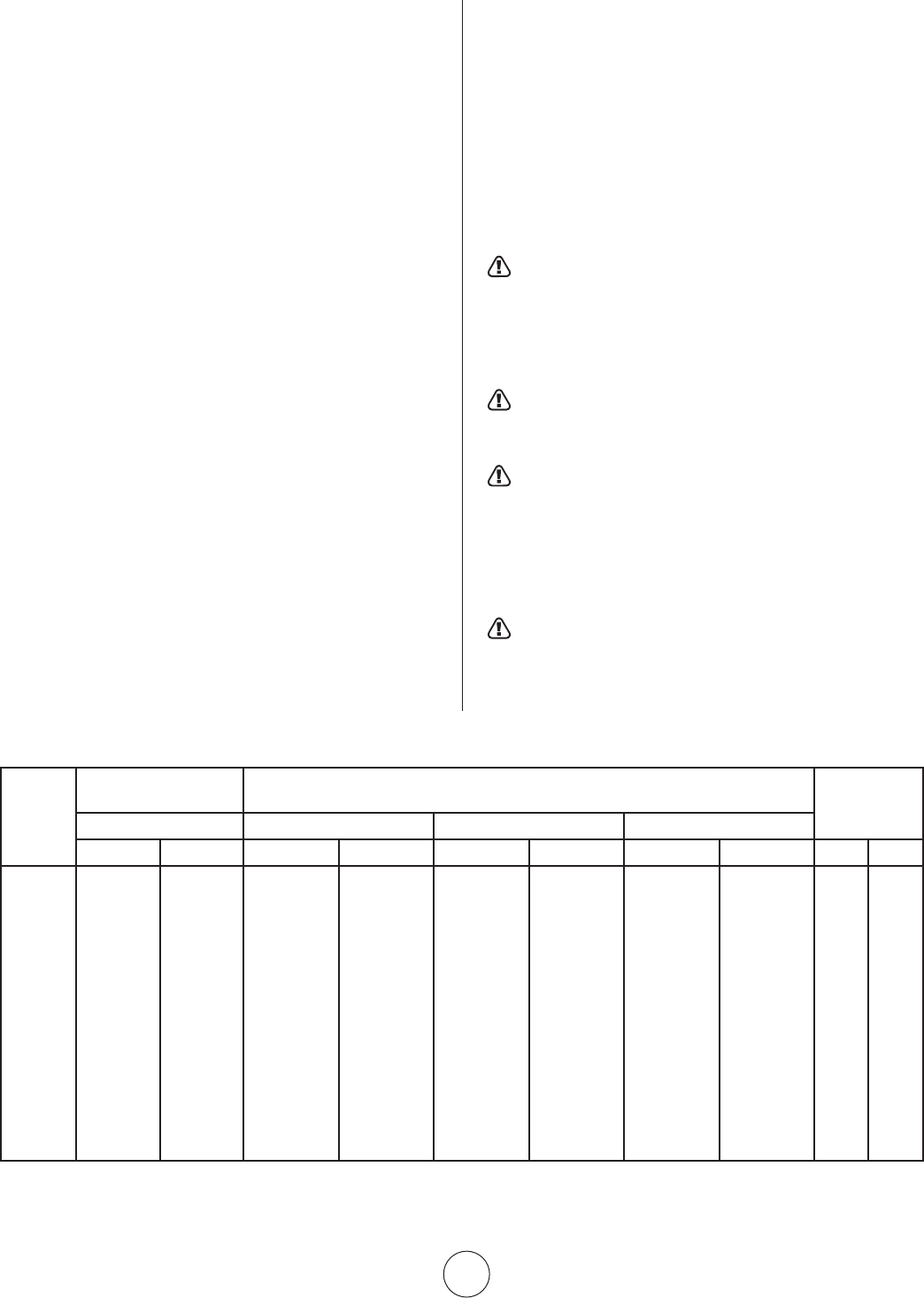
S-5
EnercoGroup,Inc.|Calentadoresinfrarrojosdealtaintensidad Instruccionesdeusoymanualdelusuario
Todoelcableadoexternodebecumplirconelcódigo
eléctricoexistente.Utiliceeldiagramadecableado
suministradoconelcalentador.Asegúresedequelas
característicasdelsuministroeléctricocoincidanconlasque
aparecen en la placa. La unidad se debe conectar a tierra
eléctricamentedeacuerdoconelCódigoEléctricoNacional,
ANSI/NFPA70,últimarevisión.EnCanadá,consulteelcódigo
eléctricocanadienseCSAC22.1
8. TERMOSTATO Y UBICACIÓN
Asegúresedequelascaracterísticaseléctricasdeltermostato
coincidan con las de los controles del calentador. Para obtener
mejoresresultados,eltermostatosedebeubicar1,52m
(5pies)porencimadelpiso,dondeelairepuedacircular
librementealrededordeél.NOLOINSTALEdirectamenteen
unaparedlateralfría,enlugaresdondehayacorrientesdeaire
directas, ni directamente debajo del calentador infrarrojo.
9. VENTILACIÓN
a.Lasaberturasmínimasdeairedeentradaysalidadeben
proporcionarnomenosde679,6m
3
/h(400CFM)porcada
entradade100.000BTUexceptoqueeláreadeinfiltraciónse
incluyaeneláreadeadmisión.Elventiladordeescapedebe
trabarse con el termostato del calentador. Si se utiliza un
ventiladordeescapeconcorriente,sedebecontrolarconel
termostato o el higrostato
b.Cuandoseproporcionaventilaciónnatural(porgravedad)
a la salida, las aberturas se deben distribuir por encima de
loscalentadores(preferentementeenlapartemásaltadel
techo)ylasáreasdelasaberturasnodebentenermenosde
0,19metroscuadrados(300pulgadascuadradas)porcada
entradade100.000BTU.
10. FUNCIONAMIENTO
Alcompletarelcableadoeléctrico,lastuberíasdegas
ylapurgacióndelaslíneasdegas,consultelaplacade
instruccionesdeencendidoqueseencuentraenelcalentador
paraobtenerinformaciónsobreelprocedimientode
encendido adecuado.
11. INFORMACIÓN DE LIMPIEZA
LimpieelVenturiyelquemadorconairecomprimido(presión
máximade11kg/cm
2
[25psi]);tambiénlimpielosorificios(vea
laFigura2paraobtenerinformaciónsobreeltamañocorrecto
delaperforación).Paraobtenerinformacióndetalladasobrelas
instruccionesdemantenimientoylimpieza,comuníquesecon
el representante local o con el fabricante.
ADVERTENCIA: ELMATERIALDELASJUNTAS
UTILIZADOENELARMADODEESTECALENTADOR
EMITIRÁ,MOMENTÁNEAMENTE,UNOLOROVAPOR.
UTILICEVENTILACIÓN(aOb)YESTOSEREVERTIRÁEN
APROXIMADAMENTE20MINUTOSYNOVOLVERÁA
SUCEDER.
ADVERTENCIA: NOINTENTEENCENDERELPILOTO
MANUALMENTEENCALENTADORESEQUIPADOSCONUN
SISTEMADEENCENDIDOPORCHISPAAUTOMÁTICO.
ADVERTENCIA: ELESTADODECALIFORNIAEXIGE
LASIGUIENTEADVERTENCIA:UNADELASSUSTANCIASQUE
SEDESPRENDEENLACOMBUSTIÓNALUSARESTEEQUIPO
ESELMONÓXIDODECARBONO,UNCOMPUESTOQUÍMICO
QUEDEACUERDOCONELESTADODECALIFORNIA
PRODUCECÁNCERYDEFECTOSDENACIMIENTO(UOTROS
DAÑOSREPRODUCTIVOS).
NOTA: UTILICELAÚLTIMAEDICIÓNDETODASLAS
NORMASANSIYCANADIENSES.
FIGURA 2
N.° DE
MODELO
ESPECIFICACIÓN
DEBTU/HR.
PRESIÓNDELSUMINISTRODEGAS(W.C.)
TAMAÑODEL
ORIFICIO
GAS MÍN. MÁX. COLECTOR
NATURAL PROPANO NAT. L.P. NAT. L.P. NAT. L.P. NAT. L.P.
4030 30.000 30.000
16,7cm(6,6")
28cm(11") 35,6cm(14") 35,6cm(14")
14,2cm(5,6")
25,4cm(10") 43 52
4040 40.000 40.000 17,2cm(6,8") 28cm(11") 35,6cm(14") 35,6cm(14")
14,7cm(5,8")
25,4cm(10") 37 49
8050 50.000 50.000 18cm(7") 28cm(11") 35,6cm(14") 35,6cm(14") 11cm(4,3") 25,4cm(10") 30 45
8060 60.000 60.000 18cm(7") 28cm(11") 35,6cm(14") 35,6cm(14")
14,7cm(5,8")
25,4cm(10") 29 43
8070 70.000 – 18cm(7") – 35,6cm(14") – 15,2cm(6") – 28 –
9080 80.000 80.000 18cm(7") 28cm(11") 35,6cm(14") 35,6cm(14")
14,7cm(5,8")
25,4cm(10") 37 49
9090 90.000 90.000 18cm(7") 28cm(11") 35,6cm(14") 35,6cm(14") 12,7cm(5") 25,4cm(10") 32 47
9100S 100.000 100.000 18cm(7") 28cm(11") 35,6cm(14") 35,6cm(14") 12,7cm(5") 25,4cm(10") 31 46
9100 100.000 100.000 18cm(7") 28cm(11") 35,6cm(14") 35,6cm(14") 11cm(4,3") 25,4cm(10") 30 45
9120 120.000 120.000 18cm(7") 28cm(11") 35,6cm(14") 35,6cm(14")
14,7cm(5,8")
25,4cm(10") 29 43
9140 140,000 – 18cm(7") – 35,6cm(14") – 14cm(5,5") – 28 –
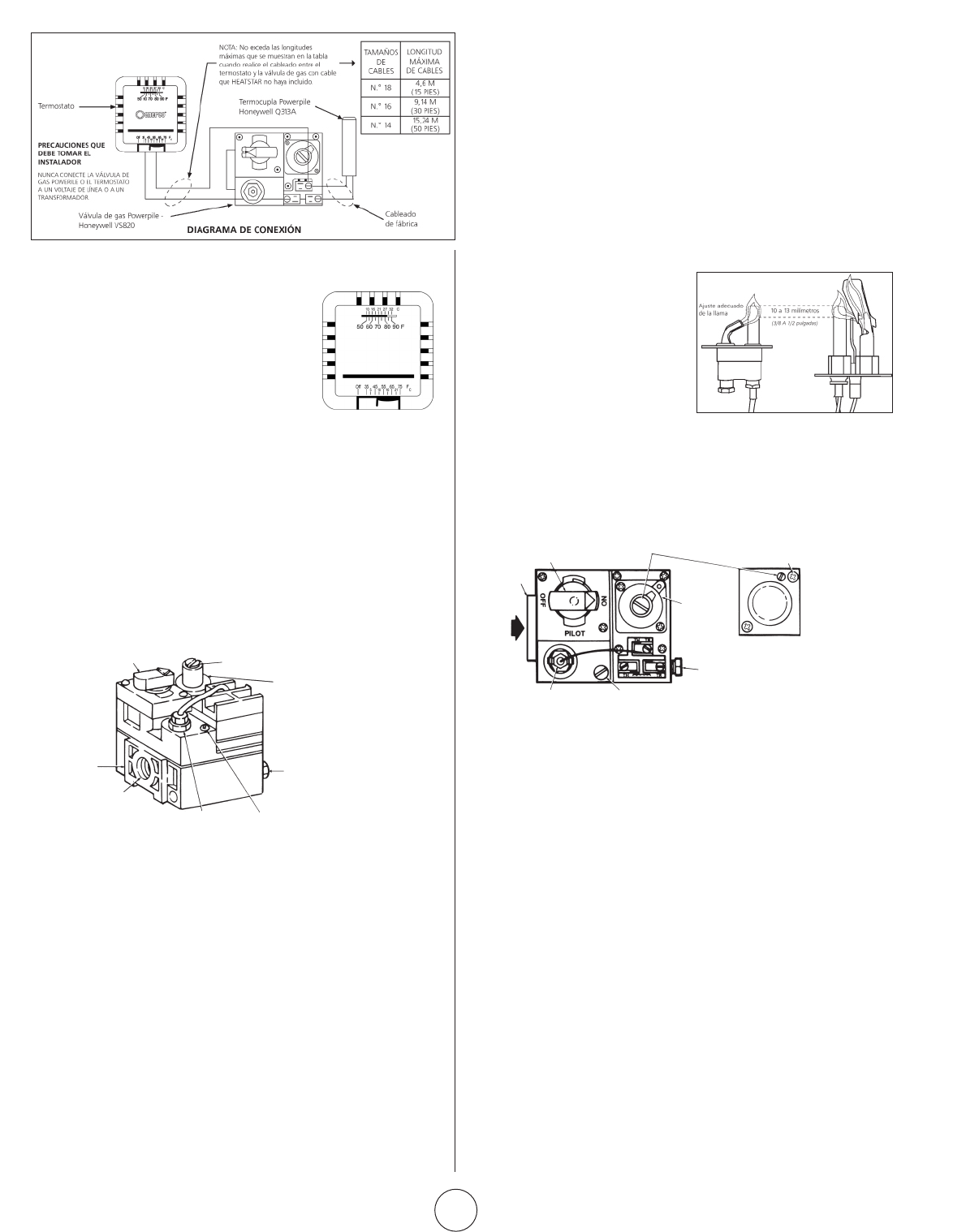
S-6
EnercoGroup,Inc.|Calentadoresinfrarrojosdealtaintensidad Instruccionesdeusoymanualdelusuario
Figura 5.
Controles del
termostato
14. INSTRUCCIONES DE MANTENIMIENTO
PARA EL OPERADOR
1. RESOLUCIÓN DE PROBLEMAS
a. LaTabla4indicalosproblemasquepuedenaparecerenel
sistema durante el uso o mantenimiento del calentador.
b. ParaobtenermásinformaciónconsulteelBoletíndecampode
Honeywelladjuntoenlacajadelcalentador.
c. Enelcasodequenoobtengaresultadosdespuésdellevar
acabotodaslassolucionesdelalista,comuníqueseconel
distribuidordeMr.Heater,oconeldepartamentodeservicio
alclientedelafábricaal1-866-447-2194.
2. AJUSTE DE LA LLAMA DEL PILOTO
La llama del piloto debe cubrir
entre10y13mm(3/8y
½pulgadas)delapuntadela
termocupla o del generador.
Paraajustarlallamadelpiloto:
12. PROCEDIMIENTO DE ENCENDIDO
ABRALA(S)VÁLVULA(S)DESUMINISTRODEGAS.
ColoqueeltermostatoenlaposiciónAPAGADO
(OFF).ConsultelaFigura5.Silaperillamanual
decontroldegasdelaválvuladegasnose
encuentraenlaposiciónAPAGADO,presione
levementelaperillaygírelahacialaposición
APAGADO.Vealafigura6.
Espere5minutosparapermitirquesalga
elgasquesepudohaberacumuladoenel
quemadorprincipal(especialmenteimportante
despuésdelainstalación).
GirelaperillamanualdecontroldegashastalaposiciónPILOTO.
Presionelaperillamanualdecontroldegas.Conunfósforo,
enciendaelpiloto.ConsultelaFigura6.Mantengalaperilla
presionadaduranteaproximadamente30segundosparapermitir
queelairequeseencuentraenlastuberíasdegaspaseporel
pilotoy,unavezqueelpilotoestéencendido,permitaquela
termocuplasecalientelosuficientecomoparaactivarlaválvulade
seguridadenunaposiciónabierta.
Sueltelaperillamanualdecontroldegasygírelahastalaposición
ENCENDIDO(ON).Configurenuevamenteeltermostatoala
temperatura deseada.
NOTA:
DuranteelencendidoinicialdeMR.HEATER,saldráunolory,
quizá,unpocodevapordelcalentador.Eselmaterialdelasjuntas
elqueemiteesteolorovapor.Despuésdeaproximadamente
20minutoselolordesapareceráyestonovolveráasuceder.
13. APAGADO
1.APAGUEeltermostato.
2.Girelaperillamanualdecontroldegasenlaválvuladegashacia
laposiciónPILOTO.
3.PresionelevementelaperillaygírelahastalaposiciónAPAGADO.
4.Cierrelasválvulasdesuministrodegas.
a. Quiteeltornillodelatapade
ajuste del piloto. Consulte la
Figura8.
b. Gireeltornillodeajusteinternohacialaderechaparadisminuir
lallamadelpilotoohacialaizquierdaparaaumentarla.
c. Siemprereemplaceeltornillodelatapadespuésdelajuste
ysujételofirmementeparagarantizarunfuncionamiento
adecuado.
Perilla manual de
control de gas
Llave
Boss
Entrada
de gas
Unidadde
alimentación
del termostato
del piloto
Ajustedelregulador
depresión(debajodel
tornillodelatapa)
Instaleun
tornillo largo
enlaesquina
externa
Regulador
depresión
estándar
(modelo
“A”)
Regulador
de la
apertura
de paso
(modelo
“C”)
Salida de
gas del
piloto(toma
depresión
directamente
debajo)
Tornillodeajustedelflujo
delpiloto(debajodel
tornillodelatapa)
Figura 8.
Vista
superior
del control
de gas de
capacidad
estándar.
15. REEMPLAZO DE LA UNIDAD DE LA
VÁLVULA DE GAS
a. Quitelosdoscablesdelaunidaddelaválvuladegasenla
válvuladecontroldegasconlaetiqueta“PP”.
b. Desenrosquelaválvuladegasdelatuberíadegas.
c. Vuelvaaconectarlaválvuladegasyloscablesdelaunidada
losterminales“PP.”Asegúresededejarelcabledeltermostato
en un terminal.
16. FRECUENCIA DE LAS VERIFICACIONES
DEL OPERADOR
Uso intermitente
Losartefactosqueseutilizantemporalmentesedebenverificar
antesdelapagadoynuevamenteantesdelpróximouso.
Ambienteconpolvo,húmedoocorrosivo.Debidoaqueestos
ambientespuedenhacerqueelcontroldegassedeterioremás
rápidamente,elsistemasedebeverificarconmásfrecuencia.
El control de gas se debe reemplazar si:
a. Nofuncionacorrectamenteenlaverificaciónoresolución
de problemas.
b. La perilla de control de gas no se puede girar o presionar
con facilidad, o no salta cuando se suelta.
TERMOSTATO
PERILLAMANUALDE
CONTROLDEGAS
LLAVE
BOSS
ENTRADA
DEGAS
AJUSTEDELREGULADOR
DEPRESIÓN
REGULADORDE
PRESIÓNESTÁNDAR
(Lapresiónentrante
noexcedelos33cm
[13"W.C.])
SALIDADEGASDEL
PILOTO(TOMADEPRESIÓN
DIRECTAMENTEDEBAJO)
TORNILLODEAJUSTEDEL
FLUJODELPILOTO(DEBAJODEL
TORNILLODELATAPA)
UNIDADDEALIMENTACIÓN
DELTERMOSTATODELPILOTO
Figura 6. Componentes
de la válvula de gas
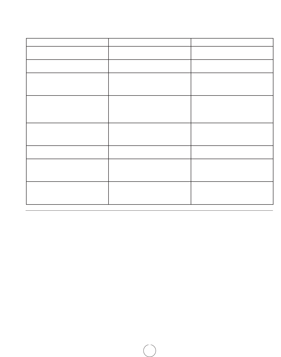
S-7
EnercoGroup,Inc.|Calentadoresinfrarrojosdealtaintensidad Instruccionesdeusoymanualdelusuario
TABLA 4. CUADRO DE RESOLUCIÓN DE PROBLEMAS
Acontinuación,enformadecuadro,seencuentranvarios
síntomasdeunsistemaconfallas,losposiblesdefectosque
causanestossíntomasylamedidacorrectivasugerida.Enel
FUNCIONAMIENTO EN ALTITUDES ELEVADAS
1. Comuníqueseconelfabricanteparaobtenerunjuegode
conversiónparaaltitudeselevadasdetalladoquesatisfaga
sus necesidades.
1.1Estépreparadopararesponderpreguntasde
fabricaciónsobre:eltipodecombustibleparalaconversión
deartefactospropuesta,lapresióndegasdisponibleenel
sitioylaaltitudespecíficaenelsitio.
2. “Unrepresentanteautorizadodelfabricantedeberealizar
laconversión,deacuerdoconlosrequisitosdelfabricante,
oporautoridadesprovincialesoterritorialesquetengan
jurisdicciónydeacuerdoconsusrequisitos.”
3. Losjuegosdeconversiónparaaltitudeselevadasincluyen
unaplacaespecíficaparaaltitudeselevadascondatos
impresos,orificiosyquemadornecasariosparanecesidades
específicaseinstruccionesdeinstalaciónadicionales.
4. EnCanadá,lasinstalacionesdecalentadoresenaltitudes
elevadasdebencumplirconlasdisposicionesde
construcciónaplicablesdelanormaCAN1-2.17actual,para
artefactosagasparausoenaltitudeselevadas.
cuadroseasumequelapresióndegasadecuadaestádisponible
paraelcalentadoryqueelprocedimientodeencendidoeselque
se menciona en la placa del calentador.
SÍNTOMAS C AUSAS SOLUCIONES
Elquemadorseapagamuylentamente Orificiodelpilotoparcialmentebloqueado
Piloto fuera del ajuste
Volveraajustarelpiloto
Reemplazar
Elquemadorseapagamuylentamente
Elcolorquedapálido
Orificiodelquemadorparcialmente
bloqueado
Reemplazar
Elquemadorretrocede
(hayunruidocrepitanteduranteel
funcionamiento y la superficie de la rejilla
decerámicaseoscurece)
Bajapresióndegas
Quemadordañado
Corregirlapresióndelíneaocomunicarse
conelproveedor
Reemplazar
Larejilladecerámicaoelquemadortiene
hollín(cuandosonnuevosodespuésde
unalimpieza)
Primeraverificaciónparaversielorificio
delquemadorestádañado
Sielorificiodelquemadornoestá
dañadoverifiqueparaversihayun
colectordañado
Reemplazarsiestádañado
Reemplazar
El piloto no se puede encender Orificiodelpilotobloqueado.Laválvula
degasnoestáensuposición
Esposiblequeeltornillodeajustedel
flujodegasdelpilotoestécerrado
Reemplazar
Girarlaperilladecontroldegashasta
piloto y mantenerla presionada
Abriryajustar(vealaFigura8)
El piloto enciende pero se apaga Termocupladefectuosa
Control defectuoso
Reemplazar
Reemplazar
Elpilotoquedaencendidoperoel
quemadorprincipalnoenciende
Cable flojo o mal conectado
Control defectuoso
Orificiodelquemadorbloqueado
Ajustarlasconexiones,verificareldiagrama
de cableado
Reemplazar
Limpiar el orificio o reemplazar
No enciende
Elsuministrodegasprincipalestáapagado
Aireenlatuberíadegas
Conexioneseléctricasflojas
Conexioneseléctricassucias
Abrirlasválvulasmanuales
Purgarlatuberíadegas
Ajustarlasconexioneseléctricas
Limpiar y sujetar los terminales
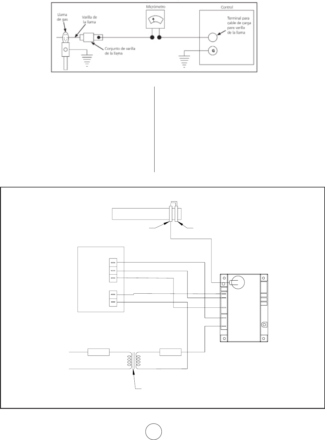
S-8
EnercoGroup,Inc.|Calentadoresinfrarrojosdealtaintensidad Instruccionesdeusoymanualdelusuario
DIAGRAMA DE CONEXIÓN DE LA CORRIENTE DE LA VARILLA DE LA LLAMA
PARA LOS SISTEMAS DE RECTIFICACIÓN DE LLAMAS (DSP-5, A5)
MEDIOS PARA DEMOSTRAR UN ÁREA DE CONEXIÓN
A TIERRA ADECUADA
Larelaciónentrelaconexiónatierraylavarilladelallama
adecuada no siempre se puede determinar mediante un
examenvisualounamediciónfísica.Unaformapositivade
verificarlainstalaciónesatravésdelamedicióndecorriente
delavarilladelallamabajocondicionesdeencendido
reales.Serecomiendaqueelinstaladormidaelflujode
corrienteentreelcabledelavarilladelallamayelterminal
enlaplacadelterminaldecontrol(consultelaFigura3).
MidalacorrienteconunmicrómetrodeCCoequivalente.
Recomendamosunasalidaestablede9microamperioso
más.Unflujoestabledecorrienteenestacantidadbajo
condiciones de encendido reales generalmente indica una
conexiónatierraadecuadadelallamadelpiloto.
NOTA:
1. Leatodalahojadedatosdecontrolsuministradaconeste
calentador.
2. Verifiquelavarilladelallamaparaversitienecontacto
conlaspiezasdelcalentador.Lavarilladelallamanodebe
tenerningúncontactoconelcalentador.Elcontactoconel
calentadorproduciráuncortocircuitoenlavarilladelallama.
3. Lapresenciadeporcelanafisuradaenlavarilladelallama
produciráuncortocircuitoenelsensor.Reemplacelavarilla
de la llama.
Figura 3:Utilizacióndeunmicrómetroparademostrarunáreadeconexiónatierraadecuada.
GND
V2
FENWALL
IGNITION MODULE
IND/
MV1
V1/PV1
TH/W
SPARK
120VAC
24VAC
24 VOLT
THERMOSTAT
OPTIONAL
LINE VOLTAGE
THERMOSTAT
OPTIONAL
TRANSFORMER
(SHIPPED LOOSE)
GAS VALVE
PV
PV/MV
MV
VALVE
GROUND
MAIN BURNER
PILOT BURNER
SPARK ELECTRODE/FLAME SENSOR
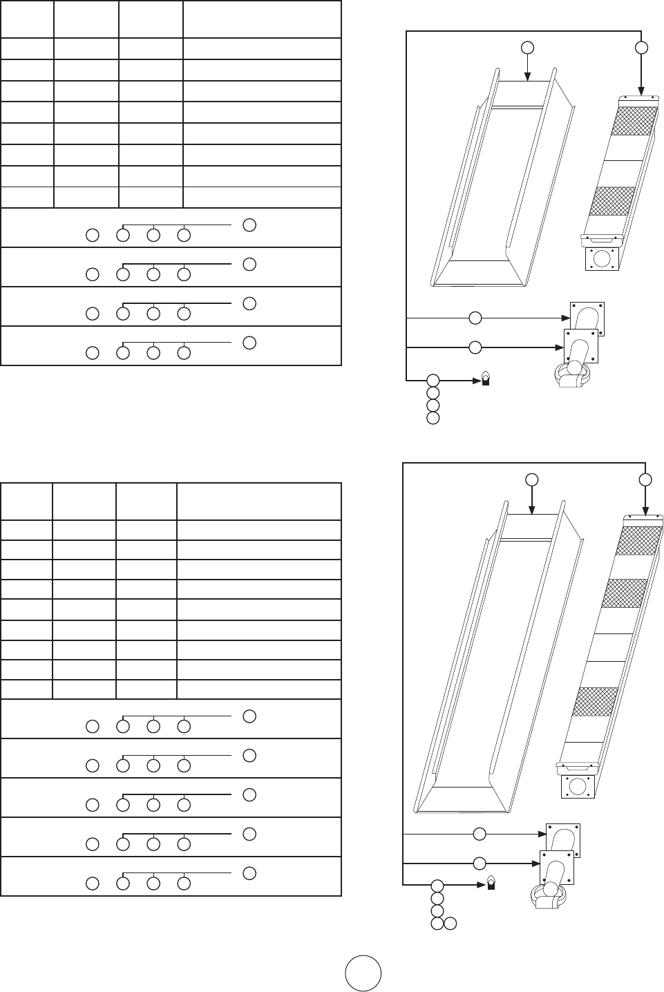
S-9
EnercoGroup,Inc.|Calentadoresinfrarrojosdealtaintensidad Instruccionesdeusoymanualdelusuario
Lista de repuestos para modelos de calentadores
de serie 4000 / Menos control
N.ºde
artículo
Cantidad
necesaria
N.ºde
inventario
Descripción
1 1 00435A Conjunto de reflector
2 1 02523A Conjuntodequemador
3 1 03397P Venturi
4 1 05437 Orificio–Br.N.G.4040
5 1 05443 Orificio–Br.N.G.4030
6 1 05449 Orificio–Br.L.P.4040
7 1 05452 Orificio–Br.L.P.4030
8 1 1236 6 Junta–Venturi
1 3 5 9
4040Gasnatural
2
o
1 3 6 9
4040Gasnatural
2
o
1 3 7 9
4040Propano
2
o
1 3 8 9
4040Propano
2
o
Lista de repuestos para modelos de calentadores
de serie 8000 / Menos control
N.ºde
artículo
Cantidad
necesaria
N.ºde
inventario
Descripción
1 1 00442A Conjunto de reflector
2 1 02524A Conjuntodequemador
3 1 03421P Venturi
4 1 05428 Orificio–Br.N.G.8070
5 1 05429 Orificio–Br.N.G.8060
6 1 05430 Orificio–Br.N.G.8050
7 1 05443 Orificio–Br.L.P.8060
8 1 05445 Orificio–Br.L.P.8050
9 1 1236 6 Junta–Venturi
1 3 5 10
8070Gasnatural
2
o
1 3 6 10
8060Gasnatural
2
o
1 3 7 10
8050Gasnatural
2
o
1 3 8 10
8060Propano
2
o
1 3 9 10
8050Propano
2
o
5
6
7
8
1 2
9
3
5
6
7
8 9
1 2
10
3
5
6
7
8
1 2
9
3
5
6
7
8 9
1 2
10
3
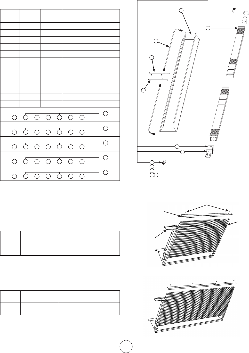
S-10
EnercoGroup,Inc.|Calentadoresinfrarrojosdealtaintensidad Instruccionesdeusoymanualdelusuario
Lista de repuestos para modelos de calentadores
de serie 9000 / Menos control
N.ºde
artículo
Cantidad
necesaria
N.ºde
inventario
Descripción
1 1 00444A Conjunto de reflector
2 2 02694 Conjuntodequemador
3 2 03421P Venturi
4 2 05428 Orificio–Br.N.G.9140
5 2 05429 Orificio–Br.N.G.9120
6 2 05430 Orificio–Br.N.G.9100
7 2 05443 Orificio–Br.L.P.9120
8 2 05445 Orificio–Br.L.P.9100
9 2 06396 Conjunto del colector
10 2 12366 Junta–Venturi
11 1 14639 Soporte del asiento central
12 1 113 81 Conjunto de soporte central
9140Nat.Gas
1 3
10
4
11
9
12
2
or
9120Nat.Gas
1 3
10
7
11
9
12
2
or
9100Nat.Gas
1 3
10
6
11
9
12
2
or
9120Propane
1 3
10
7
119 12
2
or
9100Propane
1 3
10
8
119 12
2
or
1
11
15
14
7
8
9 10
12
6
3
2
F104440 GriddecorativaKit Rejilla, tornillos, clip de
retención
F104441 RetroGridKit Reflector, rejilla, tornillos, clip
deretención
Piezas de recambio para Retro Grid Kit
Modelos de la serie 4000 y modelos de la serie 8000 SOLAMENTE
F104445 GriddecorativaKit Rejilla, tornillos, clip de
retención
F104446 RetroGridKit Reflector, rejilla, tornillos, clip
deretención
Grid
ClipdeRetención
Tornillos
Reflector
Modelos de la serie 4000
Modelos de la serie 8000
4000SERIES
8000SERIES
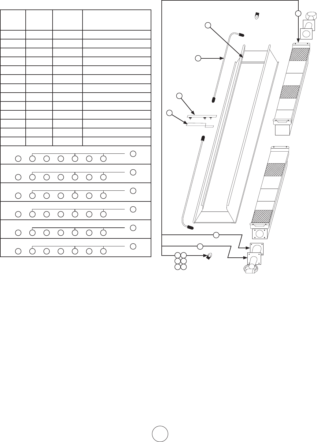
S-11
EnercoGroup,Inc.|Calentadoresinfrarrojosdealtaintensidad Instruccionesdeusoymanualdelusuario
Lista de repuestos para modelos de calentadores
de serie 9100S / Menos control
N.ºde
artículo
Cantidad
necesaria
N.ºde
inventario
Descripción
1 1 00443A Conjunto de reflector
2 2 02508A Conjuntodequemador
3 2 03421P Venturi
4 2 05431 Orificio–Br.N.G.9100S
5 2 05432 Orificio–Br.N.G.9090
6 2 05437 Orificio–Br.N.G.9080
7 2 05446 Orificio–Br.L.P.9100S
8 2 05447 Orificio–Br.L.P.9090
9 2 05449 Orificio–Br.L.P.9080
10 2 06398 Conjunto del colector
11 2 1236 6 Junta–Venturi
12 1 14639 Soporte del asiento central
13 1 113 81 Conjunto de soporte central
9100SNat.Gas
1 3
11
4
1210 13
2
or
9090Nat.Gas
1 3
11
5
1210 13
2
or
9080Nat.Gas
1 3
11
6
1210 13
2
or
9100SPropane
1 3
13
7
1210 13
2
or
9090Propane
1 3
13
8
1210 13
2
or
9080Propane
1 3
13
9
1210 13
2
or
15
12
1
6 7
8 9
10 11
2
16
3
13
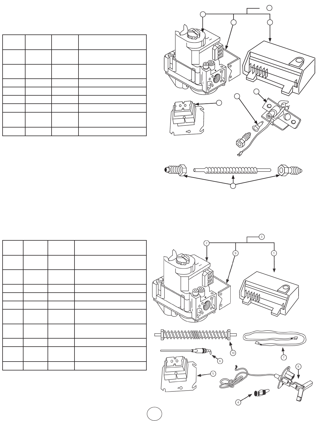
S-12
EnercoGroup,Inc.|Calentadoresinfrarrojosdealtaintensidad Instruccionesdeusoymanualdelusuario
HEAT STAR DE SERIE 4000, 8000 (NG)
LISTA DE REPUESTOS PARA EL SUFIJO DEL
SISTEMA DE CONTROL
N.ºde
artículo
Cantidad
necesaria
N.ºde
inventario
Descripción
1 1 00063 Módulodeencendido,
FENWAL
2 1 00037 VálvuladegasNG/
VR8204A2001/SWC
3 1 00228 Conj. De control NG
4 1 05573 Orificio para el piloto GN
5 1 08353 Transformador40VA
6 1 114 0 3 Conj.Dequemadordelpiloto
7 1 14615 Montaje del soporte
A5,745RS,l&Hon.V.
8 1 16425 Tubodelpilotoflexc/acoples
HEAT STAR DE SERIE 9000SP, 9000SSP (NG)
LISTA DE REPUESTOS PARA EL SUFIJO DEL SISTEMA
DE CONTROL
N.ºde
artículo
Cantidad
necesaria
N.ºde
inventario
Descripción
1 1 00063
Módulodeencendido,
FENWAL
2 1 00037
VálvuladegasNG/
VR8204A2001/SWC
3 1 00228 Conj. De control NG
4 1 05383 Orificioparaelpiloto–NG
5 1 08353 Transformador40VA
6 1 09374
Sondat/c112,7/81,28cm
(5/32")delargo
7 1 09375
Cableparasondas4000,8000,
9000HTRS.
8 1 113 85 Conj.Dequemadordelpiloto
9 1 14 615
Montaje del soporte A5,745RS,
l&Hon.V.
10 1 16425 Tubodelpilotoflexc/acoples
5
1
3
2
or
4
6
8
7
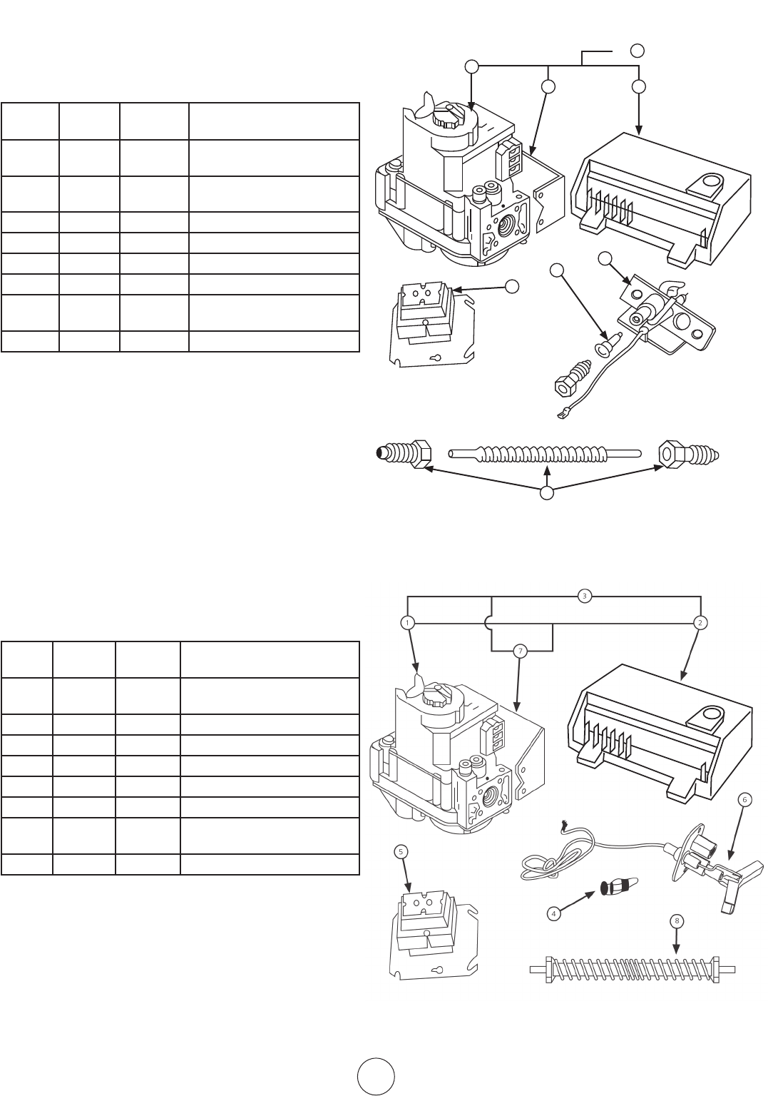
S-13
OperatingInstructionsandOwner’sManualEnercoGroup,Inc.|Gas-FiredInfra-RedSpaceHeaters
PARA HEAT STAR DE SERIE 4000, 8000
HEAT STAR DE SERIE 4000SP, 8000SP (LP)
LISTA DE REPUESTOS PARA EL SUFIJO DEL SISTEMA
DE CONTROL SP
N.ºde
artículo
Cantidad
necesaria
N.ºde
inventario
Descripción
1 1 00036
VálvuladegasLP/
VR8204A2092/11"WC
2 1 00063
Módulodeencendido
FENWAL
3 1 00329 Conj. De control LP
4 1 05577 Orificioparaelpiloto–LP
5 1 08353 Transformador40VA
6 1 114 0 7 Conj.Dequemadordelpiloto
7 1 14 615
Montaje del soporte,745RS.
l.&Hon.V.
8 1 16 425 Tubodelpilotoflexc/acoples
HEAT STAR DE SERIE 9000SP, 9000SSP (LP)
LISTA DE REPUESTOS PARA EL SUFIJO DEL SISTEMA
DE CONTROL SP
N.ºde
artículo
Cantidad
necesaria
N.ºde
inventario
Descripción
1 1 00036
VálvuladegasLP/
VR8204A2092/11"WC
2 1 00063 MódulodeencendidoFENWAL
3 1 00329 Conj. De control LP
4 1 05384 Orificioparaelpiloto–LP
5 1 08353 Transformador40VA
6 1 113 8 5 Conj.Dequemadordelpiloto
7 1 14 615
Montaje del soporte,745RS. l.
&Hon.V.
8 1 16425 Tubodelpilotoflexc/acoples
5
1
3
2
or
4
6
8
7
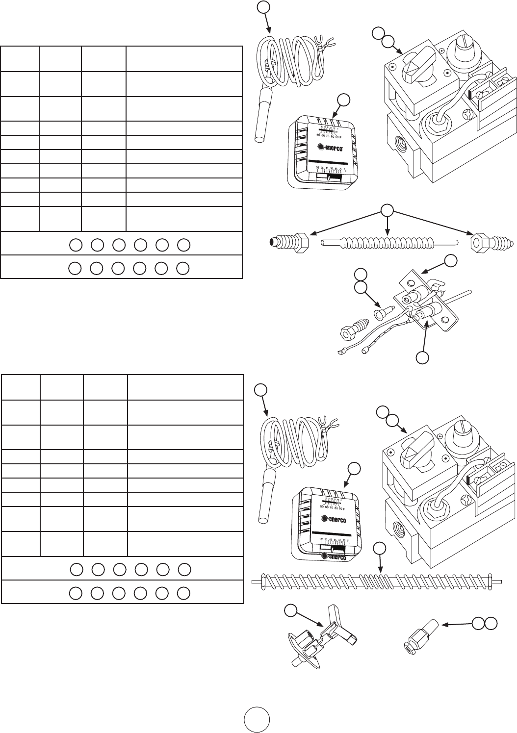
S-14
EnercoGroup,Inc.|Gas-FiredInfra-RedSpaceHeaters OperatingInstructionsandOwner’sManual
PARA HEAT STAR DE SERIE 4000, 8000
LISTA DE REPUESTOS PARA EL SUFIJO DEL SISTEMA
DE CONTROL NPP, LPP
N.ºde
artículo
Cantidad
necesaria
N.ºde
inventario
Descripción
1 1 00024
Válvuladegascombinada
(PP)GN1/2x1/2NPT
2 1 00025
Válvuladegascombinada
(PP)LP1/2x1/2NPT
3 1 05577 Orificio para el piloto LP
4 1 05573 Orificio para el piloto GN
5 1 09360 TermocuplaPPHoneywell
6 1 10367 Termostato“PP”Heatstar
7 1 114 0 5 Piloto-PP-4K,8KHTRGN
7 1 11408 Piloto-PP-4K,8KHTRLP
8 1 16425
Tubodelpilotoflexcon
acoples
NPP
1 4 5 6 7 8
LPP
2 3 5 6 7 8
1
4
5
6
7
8
2
3
1
5
3
6
2
8
4
5
7
1
4
5
6
7
8
2
3
1
5
3
6
2
8
4
5
7
PARA HEAT STAR DE SERIE 9000, 9000S
LISTA DE REPUESTOS PARA EL SUFIJO DEL SISTEMA
DE CONTROL NPP, LPP
N.ºde
artículo
Cantidad
necesaria
N.ºde
inventario
Descripción
1 1 00024
Válvuladegascombinada
(PP)GN1/2x1/2NPT
2 1 00025
Válvuladegascombinada
(PP)LP1/2x1/2NPT
3 1 05384 Orificio para el piloto LP
4 1 05383 Orificio para el piloto GN
5 1 09360 TermocuplaPPHoneywell
6 1 10367 Termostato“PP”Heatstar
7 1 113 8 5
Quemadordelpiloto-
9000HTR
8 1 16425
Tubodelpilotoflexcon
acoples
NPP
1 4 5 6 7 8
LPP
2 3 5 6 7 8
NOTA:1–ALHACERUNPEDIDODEREPUESTOSPROPORCIONE
SIEMPREELN.ºDEMODELO,N.ºDEINVENTARIO,N.º
DESERIEYTIPODECALENTADOROGASUTILIZADO.
2–ALDESARMARLASPIEZASDELCALENTADORPARASU
REPARACIÓN,PRESTEATENCIÓNALAPOSICIÓNDE
LASPIEZAS,YLUEGOINVIERTAELPROCEDIMIENTO
CUANDOLASENSAMBLE.
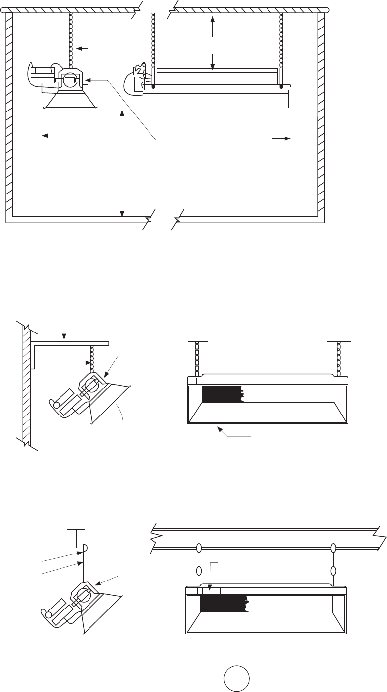
S-15
OperatingInstructionsandOwner’sManualEnercoGroup,Inc.|Gas-FiredInfra-RedSpaceHeaters
MÉTODOSUGERIDOPARAELCOLGADO
MODELOS:4000,8000,9000,MH40
MONTAJE TÍPICO PARA VIGAS
FIGURA 4
CIELORRASO
LATE-
RAL
PARED
PISO
MONTAJE HORIZONTAL
POS-
TE-
RIOR
LEALASINSTRUCCIONESDEINSTALACIÓNPARA
OBTENERINFORMACIÓNDETALLADASOBRE
LASDISTANCIAS
DISTANCIA A COMBUSTIBLES
INFERIOR
SUPERIOR
ABRAZADERA
PARAVIGAS
VARILLAROSCADA
CUANDOELMONTAJEANGULAR
ELEVESÓLOELCOSTADO
DESIGNADODELCALENTADOR
FIGURA 5
ÁNGULODEHIERRO
VERJUEGO
DECADENAS
N.º17374
OVARILLA
ROSCADA
DEL
MÁXIMO
HORIZONTAL
45°
MONTAJE TÍPICO PARA PAREDES
ELREFLECTORLATERALDEL
CALENTADORDEBEESTAR
PARALELOALPISO
MONTAJE
VERJUEGO
DECADENAS
N.º17374
OVARILLA
ROSCADA
JUEGODE
SOPORTEPARA
COLGARF114581
JUEGODE
SOPORTEPARA
COLGARF114581
OJUEGODE
CADENAS17374
SERECOMIENDA
USARELSOPORTE
F114581PARA
COLGAREL
CALENTADOR
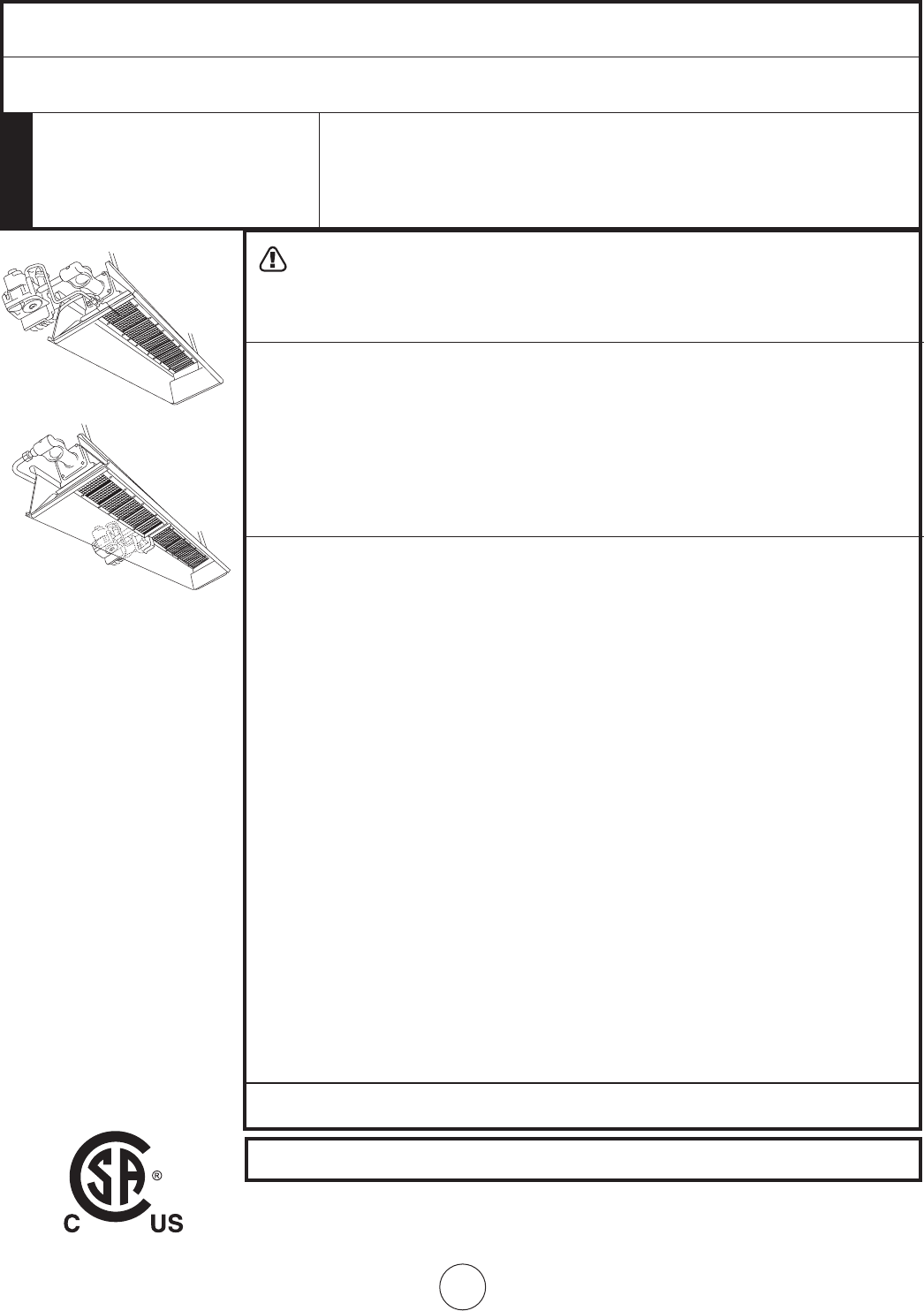
S-16
EnercoGroup,Inc.|Gas-FiredInfra-RedSpaceHeaters OperatingInstructionsandOwner’sManual
ADVERTENCIA: USESOLAMENTEREPUESTOSDELFABRICANTE.EL
USODECUALQUIEROTRAPIEZAPODRÍACAUSARHERIDASOLAMUERTE.LOS
REPUESTOSESTÁNDISPONIBLESÚNICAMENTEENLAFÁBRICAYDEBENSER
INSTALADOSPORUNAAGENCIADESERVICIOCALIFICADA.
INFORMACIÓN PARA PEDIR REPUESTOS:
COMPRAS: PuedecompraraccesoriosencualquierdistribuidorlocaldeMr.Heater/Heatstar
odirectamentedelafábrica.
SI DESEA OBTENER INFORMACIÓN ACERCA DE REPARACIONES
Llamesincargoal866-447-2194•www.enerco-mrheater.com
Nuestrohorariodetrabajoesde8:30a.m.a5:00p.m.,horadeleste,delunesaviernes.
Envíeuncorreoelectrónicoa:techservice@enerco-mrheater.com
Incluyaelnúmerodemodelo,lafechadecomprayladescripcióndelproblemaentodassus
comunicaciones.
GARANTÍA LIMITADA
Lacompañíadagarantíasdequeesteproductoestálibredeimperfeccionesmaterialesyde
fabricación,bajo condiciones de uso normales y adecuadas de acuerdo con las instrucciones de la
Compañía,porunperíododeunañoapartirdelafechadeentregaalcomprador.LaCompañía,
segúndecida,repararáoreemplazarálosproductosqueelcompradordevuelvaalafábrica,
contransportaciónprepagadadentrodelmencionadoperíododeunañoyquelaCompañía
determinequepresentanimperfeccionesmaterialesodefabricación.
Garantíaprorrateadade10añossóloparaelconjuntodelquemador.
Sialgunadelaspiezasestádañadaosilefaltaalguna,llamealDepartamentodeAsistencia
Técnicaal866-447-2194.
DirijasusreclamosdegarantíaalDepartamentodeServicioalasiguientedirección:EnercoGroup,
Inc.,4560W.160thSt.,Cleveland,Ohio44135.Incluyasunombre,direcciónynúmerotelefónico
ensucomunicación,ylosdetallesrelacionadosconelreclamo.Además,infórmenoslafechadela
comprayelnombreyladireccióndelproveedordequienadquiriónuestroproducto.
LoanteriordescribelasresponsabilidadesdelaCompañíaentodasuextensión.Nohayotras
garantías,niexplícitasniimplícitas.Específicamente,nohaygarantíasacercadelaadecuación
paraunpropósitoparticularynohaygarantíasdecomerciabilidad.EnningúncasolaCompañía
seráresponsablepordemorascausadasporimperfecciones,pordañosconsecuentesnipor
ningúnotrocargodegastosdeningunanaturalezarealizadossinsuconsentimientoescrito.El
costodereparaciónoreemplazoserálaúnicacompensaciónporcualquierincumplimientodela
garantía.Nohaygarantíanisederivarágarantíaimplícitaalgunadelprocesodecomercialización
nidelasprácticascomercialescomunes.Estagarantíanoseráválidaparaproductosquehayan
sidoreparadosoalteradosfueradelafábricaencualquiersentidoqueanuestrocriterioafectesu
estado o funcionamiento.
Algunosestadosnopermitenlaexclusiónolimitacióndedañosincidentalesniconsecuentes,así
quelalimitaciónoexclusiónanteriorpuedenotenervalidezensucaso.EstaGarantíaleotorga
derechoslegalesespecíficos,yustedpuedetenerotrosderechosquevaríandeunestadoaotro.
EnercoGroup,Inc.,sereservaelderechodehacercambiosencualquiermomento,sinprevio
aviso,enloscolores,especificaciones,accesorios,materialesymodelos.
ENERCOGROUP,INC.,4560W.160THST.,CLEVELAND,OHIO44135•866-447-2194
Mr.HeateresunamarcacomercialregistradadeEnercoGroup,Inc.
©2017,EnercoGroup,Inc.Todoslosderechosreservados.
ANSI Z83.19a-2011/CSA 2.35a-2011
LANGUAGES
LANGUAGES
REGISTRODELPRODUCTO:Graciasporsucompra.
Iniciesesiónenhttp://www.egiregistration.compararegistrarsuproducto.
INSTRUCCIONES DE USO Y MANUAL DEL USUARIO
LEA CUIDADOSAMENTE LAS INSTRUCCIONES: Lea y siga todas
lasinstrucciones.Conserveestasinstruccionesenunlugarseguro
parafuturareferencia.Nopermitaquenadiequenohayaleído
estas instrucciones arme, encienda, ajuste o use el calentador.
Calentadores infrarrojos de alta intensidad HEATSTAR
MODELOS
HS4030 HS8070 HS9100
HS4040 HS9080 HS9120
HS8050 HS9090 HS9140
HS8060 HS9100S
